
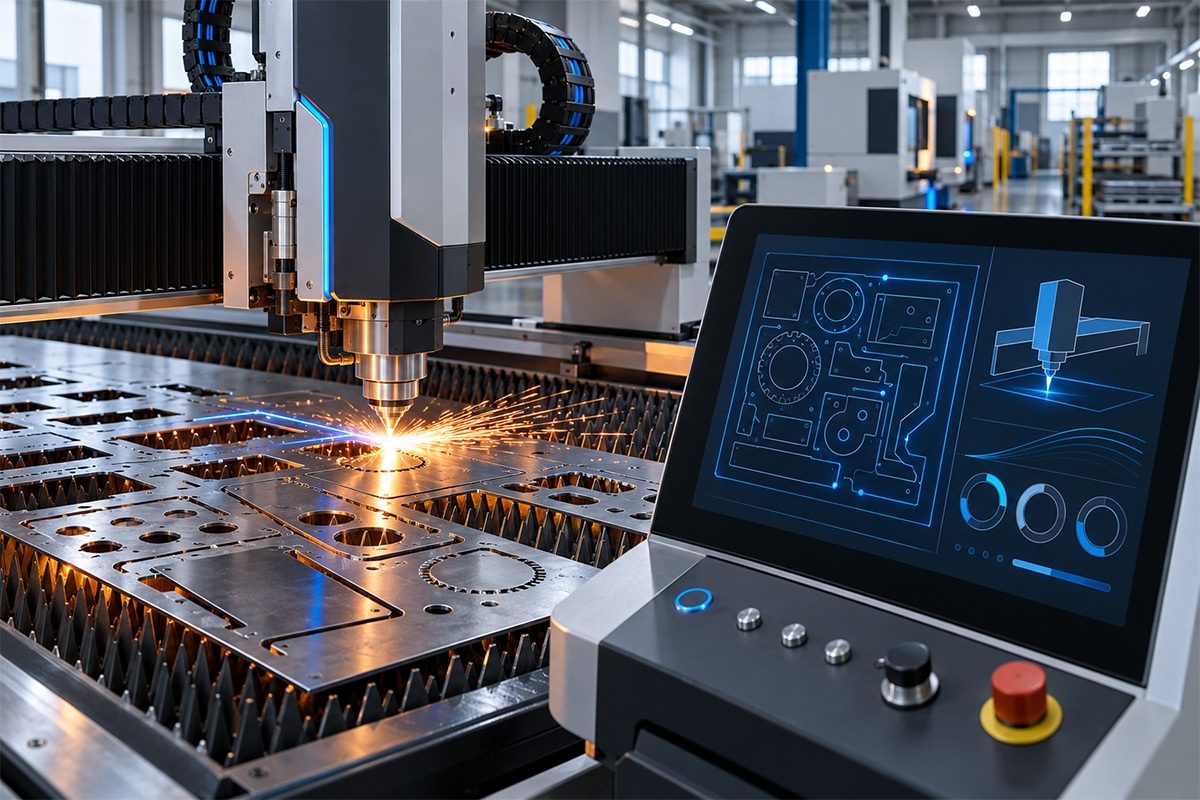
The Impact of Control Systems on Laser Cutting
Laser cutting combines concentrated energy with controlled movement to produce detailed components across a wide range of industries. Achieving accurate dimensions, clean edges, and reliable production requires close coordination between the laser source, cutting head, motion system, and process settings. The control system provides this coordination, translating programmed instructions into synchronized machine actions.
The laser cutting control system typically brings together computer numerical control (CNC), machine control logic, an operator interface, and communication with drives and sensors. Depending on the machine configuration, it manages axis positioning, cutting speed, laser output, piercing sequences, assist-gas settings, and cutting-head height. Coordinating these functions helps the machine follow programmed contours while maintaining suitable processing conditions throughout each cut.
The effects of control performance become particularly apparent when cutting sharp corners, small holes, intricate patterns, or parts requiring frequent changes in direction. As the cutting head accelerates or slows down, laser output must remain appropriate for the changing speed. Functions such as path look-ahead, coordinated power adjustment, and automatic height control can improve contour accuracy, limit excessive heat input, and support more consistent edge quality.
Control systems also influence everyday productivity and ease of operation. Clear interfaces, reusable process settings, and integration with CAD/CAM workflows can simplify setup and reduce manual input. Monitoring and recovery functions can help operators identify interruptions and resume production efficiently. These capabilities affect production time, scrap levels, and operating costs, although results also depend on machine construction, material condition, maintenance, and process setup.
Understanding the impact of control systems is therefore essential when evaluating laser cutting equipment or improving an existing operation. This article examines how control architecture, motion accuracy, process coordination, software capabilities, and operator interaction influence cutting performance, helping manufacturers assess the features that matter most for their materials, production requirements, and quality objectives.
Table of Contents
Understanding Laser Cutting Control Systems
Laser cutting depends on the coordinated operation of several components, including the laser source, motion drives, cutting head, sensors, and auxiliary equipment. The control system connects these components and organizes their actions so that a digital design can be reproduced in a physical workpiece. Its responsibilities extend from interpreting cutting instructions to coordinating movement, managing process settings, and responding to machine conditions.
Understanding how this system works provides a foundation for evaluating its influence on accuracy, cutting quality, productivity, and operating consistency. Three areas are particularly important: the functions of the control system, the workflow from design to production, and the feedback methods used to monitor and regulate performance.
What Is a Laser Cutting Control System
A laser cutting control system is the combination of hardware and software that directs a machine through a programmed cutting operation. It interprets machining instructions, coordinates the movement of individual axes, and synchronizes laser operation with the cutting path. Depending on the equipment, it also manages piercing sequences, assist-gas settings, cutting-head clearance, focus positioning, and other process functions.
Several elements usually share these responsibilities. The computer numerical control, or CNC, handles programmed movement and machining commands. A programmable logic controller, or PLC, manages machine sequences and equipment interactions. Servo drives regulate motor operation, while the human-machine interface allows operators to load programs, select settings, monitor progress, and review alarms. These functions may be integrated into one platform or distributed across connected devices.
The quality of coordination between these elements directly affects cutting performance. When a cutting head slows down to negotiate a corner, for example, the required laser output may also change. Coordinating power with movement helps control heat input and maintain edge quality. Automatic height control provides another example: it regulates nozzle clearance as the workpiece surface changes, supporting more stable processing conditions.
From Digital Design to Finished Part
The production workflow begins with a digital representation of the required component, usually created in computer-aided design software. For sheet cutting, this commonly consists of two-dimensional contours; tube and three-dimensional applications require additional geometric information. Drawing preparation establishes the correct dimensions, units, and geometry. Open contours, duplicate lines, or unintended features can otherwise become programming or cutting errors.
Computer-aided manufacturing software then turns the geometry into a cutting strategy. This includes selecting cutting directions, entry and exit paths, piercing locations, and the order in which features will be processed. Kerf compensation offsets the cutting path to account for the width of material removed by the laser. Nesting arranges parts within the available material, while optional micro-joints leave small connections that help hold selected parts in place. Some laser cutting platforms integrate drawing preparation, nesting, and CAM functions within the same software environment.
Process preparation adds settings appropriate to the material, thickness, and machine configuration. These may include cutting speed, laser output, piercing conditions, gas selection, pressure, and focus position. The resulting job is transferred to the controller using a supported program format. G-code is common, although integrated systems may use their own job formats and programming workflows. Controllers with CAM import and process-management capabilities connect these preparation steps with machine operation.
Before production begins, the operator establishes the relationship between the programmed coordinates and the actual workpiece position. The machine then executes the job by coordinating axis movement with laser activation and process commands. Motion planning determines how the axes accelerate, decelerate, and follow connected contours. Look-ahead functions examine upcoming path segments so that movement and laser output can be adjusted before reaching demanding features such as sharp corners.
During cutting, the installed feedback systems report selected machine or process conditions. Once machining is complete, the parts are removed and inspected for dimensional accuracy, edge condition, and complete separation. Depending on the application, deburring, cleaning, or further manufacturing may follow. Inspection results also help refine process settings for subsequent production runs.
Different Types of Control Feedback
Control feedback describes how measured information returns to a controller and influences its actions. The distinction applies to individual controlled variables, such as axis position, nozzle clearance, or cutting speed. A laser cutting machine can therefore combine several feedback arrangements: its motion axes may use one method, its height controller another, and its cutting process an additional monitoring system.
Open-loop control issues commands without continuously measuring whether the controlled output reaches the intended value. A stepper-driven positioning axis without position feedback is a typical example. The controller calculates movement from the commands it sends and assumes that the motor follows them correctly. This arrangement can be economical and effective within suitable operating limits. However, an overload or missed movement can create a position error that remains undetected by the positioning control.
Closed-loop control measures an output, compares it with the commanded value, and adjusts operation to reduce the difference. For axis movement, an encoder supplies position information to the drive or controller. Feedback allows the system to respond to deviations within its operating capabilities, while excessive errors may trigger an alarm. Servo systems commonly use this approach, and stepper systems can also incorporate encoder feedback. The feedback loop may operate within the motor drive or extend back to the main CNC controller.
Semi-closed-loop positioning uses feedback from the motor or another point upstream of the final moving machine element. The controller determines axis travel from measured motor rotation and the transmission relationship. Because measurement occurs before some mechanical components, errors caused by transmission backlash, wear, or thermal changes may remain outside the measured position loop. This distinction explains why accurate motor positioning alone does not describe the accuracy of the complete motion mechanism.
Fully closed-loop positioning measures the position of the driven axis more directly, typically with a linear encoder on a linear axis. Including the transmission mechanism within the position loop allows the controller to account for errors that motor feedback alone may miss. Performance still depends on encoder installation, machine geometry, structural behavior, and control tuning. Semi-closed-loop and fully closed-loop positioning are therefore different implementations of feedback control.
Height-control feedback regulates the distance between the cutting nozzle and workpiece. A distance sensor supplies information that enables the controller to adjust the relevant axis as the surface height changes. This function is especially useful when processing sheet material that is uneven or becomes distorted. Maintaining nozzle clearance is a separate control task from following the programmed cutting contour.
Process feedback and adaptive control address conditions within the cutting operation itself. On suitably equipped machines, sensors monitor process behavior and supported control functions adjust selected parameters automatically. For example, some systems observe the cutting process through the nozzle and regulate feed rate in response to changing sheet thickness or material quality. These capabilities depend on the installed sensors, software, and supported application range.
Monitoring and automatic regulation also serve different purposes. A sensor may provide an alarm or record information without continuously adjusting a cutting parameter. Likewise, changing laser power according to a programmed speed relationship does not, by itself, demonstrate feedback from the actual cut. Understanding which variable is measured, where measurement occurs, and how the controller responds gives a clearer picture of the system’s capabilities.
A laser cutting control system connects digital preparation with coordinated machine operation. It interprets cutting programs, manages movement and process commands, and uses available feedback to regulate selected conditions. The complete workflow includes design preparation, cutting-strategy development, machine setup, execution, and inspection. Open-loop control, motor-based feedback, direct axis measurement, height regulation, and adaptive process control each address different needs. Their practical value depends on how effectively they work together with the machine’s mechanics, sensors, and cutting parameters to produce consistent parts.
Main Components and Control Architectures
A laser cutting control system consists of several connected layers that translate a cutting program into coordinated physical actions. Each layer has a specific responsibility, from planning the cutting path and sequencing equipment to regulating motor movement and displaying operating information. Their interaction determines how effectively the machine maintains accuracy, responds to changing conditions, and completes production tasks.
These functions can be organized through centralized, distributed, or hybrid architectures. A centralized arrangement combines several control functions on one platform. A distributed arrangement assigns responsibilities to separate controllers, drives, and intelligent devices. Hybrid systems combine central coordination with local control. CNC, PLC, and motion functions may also run as separate software tasks on the same industrial computer, so their functional roles do not necessarily correspond to separate hardware units.
CNC and Motion Controllers
The computer numerical control, or CNC, interprets the machining program and coordinates the movements required to reproduce the part geometry. It processes instructions for straight lines, curves, cutting speeds, and machining events. Through interpolation, it generates coordinated axis commands that allow the cutting head and workpiece to follow the intended relative path. On tube and three-dimensional machines, this coordination can include both linear and rotary axes.
Motion controllers manage the execution of controlled movement. Depending on the architecture, motion control may be integrated into the CNC, implemented through dedicated hardware, or distributed between a central controller and intelligent drives. The controller plans coordinated movement, while the drives execute commands through their motor-control loops. The allocation of these tasks affects communication requirements, tuning, and the coordination of multiple axes.
For laser cutting, motion planning must also coordinate with laser operation. Look-ahead functions examine upcoming contours and prepare suitable acceleration and deceleration profiles. Laser output can then be adjusted as cutting speed changes, helping manage heat input around corners and small features. Additional functions may coordinate nozzle clearance, piercing, and transitions between cutting and travel movements. Their effectiveness depends on suitable machine settings and the response capabilities of the connected equipment.
PLCs and Machine Sequencing
Programmable logic controllers, or PLCs, organize the operating sequence of the machine and its auxiliary equipment. Typical responsibilities include managing valves, clamps, extraction equipment, material-handling devices, and readiness signals from the laser source or cooling system. The PLC evaluates input conditions and issues commands according to the current machine state.
This sequencing connects the cutting program with practical equipment operation. For example, a machining request may require confirmation that a clamp has engaged, an auxiliary device is ready, or a required operating condition has been established. The CNC and PLC exchange commands and acknowledgments so that program execution proceeds at the appropriate point. Supported synchronization methods can hold machining instructions until the PLC confirms completion of the requested action.
Well-designed sequencing also supports controlled pauses, fault handling, and recovery. Clear operating states help the system distinguish between preparation, piercing, cutting, unloading, and interrupted operation. Where safety functions are integrated, the architecture includes appropriate safety-rated controls and devices alongside the normal sequencing functions. The PLC may be a separate controller or an integrated software or hardware component within the CNC platform; integrated CNC and PLC systems are established approaches to machine control.
Servo Drives, Motors, Encoders, and Sensors
Servo drives and motors turn motion commands into physical movement. The drive supplies controlled electrical power to the motor and uses feedback to regulate its response. Servo systems commonly contain current, velocity, and position control loops. The current loop operates within the drive, while the location of the velocity and position loops depends on the system architecture. This division allows fast local regulation while maintaining coordination with the machine controller.
Motors provide the torque or linear force needed to move the cutting head, gantry, workpiece, or rotary fixtures. Their suitability depends on the moving load, required acceleration, operating speed, and mechanical transmission. Drive tuning must account for these characteristics. Excessive vibration, slow settling, or poor tracking can affect contour quality, especially when a program contains closely spaced features or frequent direction changes.
Encoders supply position information that allows the control system to compare commanded and measured movement. Motor-mounted encoders measure the motor’s output position, while external encoders can measure movement closer to the driven load. The measurement location matters because mechanical elements between the motor and load can introduce additional errors. Feedback quality, installation, and control tuning therefore influence the motion accuracy that the complete machine can achieve.
Other sensors report machine and cutting conditions. Depending on the equipment, these may include reference switches, nozzle-clearance sensors, gas-pressure sensors, cooling-system sensors, and protective-window temperature monitors. Capacitive sensing is commonly used for nozzle following in metal cutting applications, while intelligent cutting heads may combine several monitoring functions. Each signal serves a defined purpose, such as height regulation, condition monitoring, alarm generation, or supporting automatic adjustment. The presence of a sensor alone does not establish that its measured variable is automatically regulated.
Industrial Computers and Operator Interfaces
Industrial computers provide computing resources for control software, program management, process databases, diagnostics, and operator interaction. Their exact role varies by architecture. One machine may use an industrial computer mainly for the interface and job preparation, with a separate controller executing motion. Another may run CNC, PLC, and motion-control software directly on the computer through a suitable real-time control environment.
Predictable execution is essential when the computer performs time-critical control. Motion and machine-control tasks must run according to their required schedules while other activities, such as screen updates and file handling, are managed appropriately. PC-based control platforms can use real-time operating-system extensions or equivalent execution mechanisms to provide this behavior. The practical value of computing capacity therefore depends on the complete software and task architecture as well as processor performance.
The human-machine interface, or HMI, presents the system’s functions to the operator. It commonly supports program loading, parameter selection, machine-status displays, cutting previews, and alarm review. Clear workflows help operators prepare jobs and understand interruptions. Interfaces that connect alarms with relevant machine conditions can also support troubleshooting. Some platforms combine touchscreen operation, CNC control, CAM program import, and process management within a common environment, reducing the number of separate applications involved in daily operation.
Communication Networks and Synchronization
Communication links connect controllers, drives, sensors, input/output modules, and the laser source. They carry motion commands, measured values, readiness signals, and diagnostic information. Depending on the machine, communication may use industrial networks, dedicated digital connections, analog signals, or a combination of these methods. The architecture must match each connection to the timing and information requirements of its task.
For coordinated motion, predictable delivery and precise timing are essential. A high data-transfer rate alone does not describe how consistently devices update their commands or capture measurements. Timing variation, often called jitter, can affect the relationship between commanded movement and measured feedback. Motion-capable industrial networks therefore provide mechanisms for coordinating device operation. EtherCAT, for example, uses distributed clocks to establish a synchronized time reference across compatible devices.
Synchronization is also important when coordinating laser activation with position. The laser must respond at the intended location along the cutting path, particularly during short features, rapid transitions, or position-dependent processing. Supported architectures can use synchronized outputs, hardware triggering, and compensation for known device delays. These functions coordinate the controller, communication system, and laser interface so that the timing of energy delivery corresponds more closely to the intended movement.
Distributed architectures place greater importance on clearly defined communication responsibilities because multiple devices participate in control. A common hybrid arrangement uses central path planning, local drive regulation, and distributed input/output modules near the equipment they serve. Supervisory activities, such as production reporting and file transfer, can operate through separate communication paths or appropriately managed network resources. The objective is to preserve predictable control behavior while making operating information available where it is needed.
Laser cutting performance emerges from the coordinated work of several control layers. CNC and motion controllers organize the cutting path, PLCs sequence equipment, servo systems execute movement, and sensors report relevant conditions. Industrial computers and operator interfaces support software execution and daily operation, while communication networks connect the components and synchronize their actions. Centralized, distributed, and hybrid architectures allocate these responsibilities differently. Their effectiveness depends on clear task boundaries, suitable feedback, predictable timing, and reliable integration with the machine’s mechanical and laser-processing capabilities.
How Motion Control Affects Cutting Accuracy
Motion control determines how closely the actual movement of a laser cutting machine follows its programmed path. It coordinates axis positions, travel speeds, direction changes, and the dynamic response of the drive system. These functions influence dimensional consistency, hole roundness, corner definition, and the accuracy of complex profiles.
Accurate cutting requires coordinated performance throughout the motion system. The controller must interpret geometry correctly, generate a physically achievable trajectory, and guide the axes through that trajectory with suitable feedback and synchronization. Mechanical stiffness, calibration, and laser-processing conditions also contribute to the finished result. Understanding the main motion-control functions helps explain why machines with similar positioning specifications can perform differently during demanding cutting operations.
Positioning Accuracy, Repeatability, and Contour Accuracy
Positioning accuracy describes how closely an axis reaches its commanded location. It is influenced by factors such as measurement accuracy, mechanical alignment, transmission errors, calibration, and temperature. A consistent positioning offset can shift features away from their intended locations, affecting hole spacing, overall dimensions, and the relationship between separate cuts.
Repeatability describes how consistently the machine returns to the same position under comparable conditions. A highly repeatable axis can produce closely grouped results while retaining a systematic offset from the intended location. Direction of approach also matters because backlash, friction, and mechanical hysteresis can affect repeated positioning differently. Accuracy and repeatability therefore describe related aspects of performance that require separate consideration.
Contour accuracy describes how closely the actual path follows the intended geometry while the axes are moving together. It becomes especially important for circles, small holes, curves, and closely spaced direction changes. An axis may reach its final position accurately after settling while showing larger deviations during continuous movement. Circular and free-form motion tests help reveal this dynamic behavior, including errors that become apparent under higher axis acceleration.
For laser cutting, the resulting edge also depends on kerf compensation, beam characteristics, material response, and thermal distortion. Motion accuracy establishes the path of the cutting process, while these additional factors influence how that path becomes the finished part boundary.
Interpolation and Complex Geometry
Interpolation is the process of calculating intermediate movement commands between programmed geometric elements. During a straight cut, the controller coordinates the axes so that their combined movement follows the required line. During circular interpolation, individual axis speeds change continuously to maintain the intended curved path. Consistent coordination is essential because differences in axis response can distort the resulting contour.
Complex designs place greater demands on interpolation. Decorative patterns, small radii, narrow slots, and detailed profiles may contain numerous short segments. If curved geometry is represented by relatively coarse straight segments, the programmed path itself can contain visible faceting. Very dense segmentation creates a different challenge by increasing the number of blocks the controller must process while maintaining continuous movement.
Controllers may support circular interpolation, spline interpolation, and contour-smoothing functions to handle these geometries. Suitable spline methods can create smoother movement through a sequence of points, while smoothing functions can reduce abrupt transitions between segments. Their operation depends on defined geometric tolerances, which limit how far the generated path may depart from the programmed contour.
This tolerance requires careful allocation. Excessive smoothing can alter sharp corners or small features, while very restrictive settings may force frequent speed reductions. Effective interpolation preserves the required geometry while generating movement that the physical machine can follow reliably. The quality of the original CAD/CAM data remains important because interpolation operates on the geometry supplied to the controller.
Look-Ahead and Trajectory Planning
Look-ahead allows the controller to examine upcoming program blocks before executing them. This gives the trajectory planner advance information about approaching corners, changing curvature, short segments, and other features that may require a speed adjustment. The controller can then begin decelerating early enough to reach a suitable speed at the demanding feature. Look-ahead buffers provide the program information used for braking-distance calculations and dynamic planning.
Trajectory planning combines this geometric information with the configured limits of the machine. It considers how quickly individual axes can move, accelerate, and change acceleration while remaining within permitted path deviations. At a mathematically sharp corner, a finite-acceleration machine cannot maintain an unchanged nonzero speed through an instantaneous direction change. The planner must reduce speed, stop where required, or generate an allowable blended transition.
These decisions affect both geometric accuracy and the cutting process. A sudden or poorly coordinated slowdown can change the heat delivered to a local area, particularly around corners and small features. Laser-specific control functions can coordinate axis feed rate with laser output and pulse settings to help maintain suitable processing conditions through these transitions. The appropriate relationship depends on the validated cutting process and material.
The practical value of look-ahead depends on more than the advertised number of buffered blocks. Segment length, program structure, processing capacity, and the machine’s actual dynamic limits all influence the available planning horizon. A useful trajectory is one that the machine can execute accurately throughout the complete contour.
Acceleration, Deceleration, and Jerk Control
Acceleration and deceleration determine how quickly the machine increases or decreases its velocity. They are particularly important when cutting small components, repeated holes, or profiles with frequent changes in direction. On short paths, much of the movement may occur during acceleration and braking, leaving little opportunity to reach the programmed maximum cutting speed.
Direction changes also create acceleration demands. Even when the cutting speed remains constant around a curve, the direction of movement changes continuously. Tight curves therefore place significant demands on axis coordination and drive response. If the selected motion limits exceed what the machine can follow reliably, tracking errors and structural vibration may affect the contour.
Jerk describes how quickly acceleration changes. Abrupt acceleration changes can excite mechanical vibration in the gantry, cutting head, and supporting structure. Jerk-limited profiles introduce more gradual transitions, helping reduce vibration excitation and mechanical impacts. Suitable profiles can improve the stability of motion during demanding contouring operations.
The settings involve a balance between responsiveness and smoothness. Long acceleration ramps can increase cycle time, while aggressive ramps can produce oscillation or larger tracking errors. Appropriate settings depend on moving mass, structural stiffness, drive capability, and the geometry being cut. Their effect on local cutting speed also needs coordination with the laser-processing parameters.
Servo Tuning, Feedforward, and Gantry Synchronization
Servo tuning adjusts the control-loop settings so that each axis follows its commands with suitable responsiveness and stability. These settings must account for the motor, drive, mechanical transmission, moving load, and structural behavior. Insufficient responsiveness can allow larger following errors, while excessive control gains can cause overshoot, vibration, or unstable movement. In coordinated cutting, differences between axis responses can become contour errors.
Filtering can help manage mechanical resonance and noisy feedback. However, filter selection also affects the control system’s response, and some arrangements introduce additional phase lag. Effective tuning therefore considers the complete motion behavior, including how the axes respond during realistic cutting trajectories. A smooth movement on a simple test path may provide limited evidence of performance on a complex production contour.
Feedforward improves tracking by using information about the commanded movement to anticipate the required drive response. Velocity and acceleration feedforward, for example, can help reduce the lag that occurs during changing motion. These functions operate alongside feedback control, which continues to respond to measured deviations. Their effectiveness depends on appropriate modeling and adjustment; excessive compensation can cause an axis to lead the command or overshoot, reducing contour accuracy.
Gantry synchronization becomes important when separate motors drive opposite sides of a bridge. Both sides must maintain the intended positional relationship as the gantry accelerates, travels, and decelerates. Unequal movement can skew the bridge, affect machine squareness, and introduce mechanical stress. The control architecture therefore coordinates the coupled axes and may monitor their relative position against configured limits. Referencing procedures establish the required relationship between the axes according to the machine’s design.
Electronic synchronization works together with mechanical alignment, suitable feedback, and matched drive behavior. Its practical effect should be assessed across the working area and under representative operating conditions. Motion measurements help identify tracking and coordination errors, while inspection of actual cut parts shows how those errors interact with the laser process.
Motion control affects cutting accuracy through the combined performance of geometry interpretation, trajectory planning, dynamic limits, and axis regulation. Positioning accuracy establishes location, repeatability supports consistency, and contour accuracy describes path fidelity during movement. Interpolation and look-ahead prepare suitable trajectories, acceleration and jerk settings manage dynamic behavior, and servo tuning, feedforward, and gantry synchronization help the machine execute those trajectories. Reliable results depend on matching these functions to the machine’s mechanical capabilities and validating performance with representative contours and cutting conditions.
Controlling Laser Output and Cutting Parameters
Consistent laser cutting requires coordinated control of energy delivery, machine movement, piercing, and assist gas. Each parameter influences how the material heats, melts, reacts, and separates. The control system organizes these interactions so that suitable processing conditions are maintained throughout the cutting cycle.
This coordination becomes particularly important during acceleration, cornering, piercing, and transitions between features. Settings that work well along a straight contour may require adjustment when the cutting head slows down or begins a new cut. Effective control therefore combines synchronized commands, compatible laser interfaces, reliable sequencing, and validated parameter libraries. The resulting performance depends on both the controller’s capabilities and the response of the connected equipment.
Synchronizing Laser Output With Actual Motion
Laser output must remain appropriate for the cutting speed during program execution. When the cutting head slows down, a given area remains exposed to the beam for longer. Maintaining unchanged output through a substantial slowdown can increase local heating, affecting kerf width, corner definition, and edge condition. Conversely, insufficient output during faster movement can contribute to incomplete separation.
The relevant speed includes acceleration, deceleration, corner slowdowns, and supported feed-rate overrides. Depending on the architecture, synchronization uses the executing motion trajectory, feedback-derived movement information, or a combination of these. Laser-specific control functions can coordinate power and pulse settings with axis motion so that energy delivery follows the changing requirements of the path.
Beam activation and deactivation also need precise timing. The controller must coordinate emission with the start and end of each cutting segment, including small features and closely spaced cuts. Communication delays and the laser source’s response time influence where energy actually reaches the workpiece. Appropriate synchronization and compensation for known delays help align the physical cutting action with the intended geometry.
For suitable pulsed applications, position-synchronized triggering provides another approach. Compatible systems can generate laser-trigger outputs in response to real-time position feedback, allowing pulse placement to follow distance traveled. Other implementations derive triggering from commanded vector motion. These approaches have different feedback arrangements, so the synchronization method should be understood when assessing a system’s capabilities.
Power Modulation and Source Compatibility
Power modulation changes how laser energy is delivered over time. Depending on the source, the controller may adjust the output level, switch emission on and off, or control supported pulse characteristics. Continuous-wave operation delivers energy continuously during an enabled cutting interval, while pulsed or gated operation introduces interruptions. Selecting the operating mode forms part of establishing suitable cutting conditions for the material and feature being processed.
Common control terms include power level, modulation frequency, pulse duration, and duty cycle. Modulation frequency describes how often the output pattern repeats, while duty cycle describes the proportion of each modulation period during which emission is enabled. The available settings depend on the laser design. Dedicated pulsed sources and modulated continuous-wave sources can have substantially different relationships between peak output, average output, and pulse duration.
Compatibility therefore extends beyond the ability to send an activation command. The controller and source must agree on supported operating modes, signal formats, power-command scaling, timing, and operating limits. Different source models can have different modulation-frequency limits and usable power ranges. Supported pulse-shaping functions also vary; some quasi-continuous-wave sources, for example, allow analog control of individual pulse shapes.
The connection may use analog power commands, digital gating, industrial communication, or a manufacturer-specific interface. Suitable interface hardware and software allow compatible third-party sources to work with the machine controller while maintaining coordinated power control. Integration must account for the particular source and its documented functions.
Commanded power and delivered optical power also represent different quantities. A displayed percentage identifies a control setting whose physical meaning depends on the source configuration and calibration. Where optical-power measurements or source diagnostics are available, they provide additional information for evaluating output consistency. Automatic adjustment based on measured optical power requires an implemented feedback function.
Piercing Control
Piercing creates the initial opening through the material before the cutting head follows the main contour. During this stage, energy is concentrated near one location, and molten material must escape before a stable through-cut is established. The piercing sequence therefore has its own processing requirements, which can differ considerably from those used during continuous cutting.
Controllers may support single-stage or multistage piercing. A staged sequence changes selected conditions as penetration develops, coordinating laser output with gas delivery and the transition into cutting. Depending on the machine, the sequence may also include changes in nozzle height, focus position, pulse settings, and dwell time. Laser CNC systems can manage separate piercing and cutting conditions and change output through defined piercing stages.
Timed piercing uses a predefined sequence and duration established through process testing. Sensor-assisted piercing adds information about the developing process. On suitably equipped systems, breakthrough detection allows the machine to begin cutting after penetration is identified. This can reduce unnecessary waiting when the required piercing time varies, although the capability depends on the installed sensors, detection method, and supported application.
Piercing quality affects the beginning of the finished cut. An unsuitable sequence can create excessive spatter, a large entry crater, or incomplete penetration. Piercing location and lead-in geometry therefore form part of the overall strategy, particularly when small features leave limited space for an entry point. Reliable control includes a suitable transition from piercing conditions to steady cutting conditions, with results verified on representative material.
Assist-Gas Control
Assist gas helps remove molten material from the kerf and influences the cutting reaction and edge condition. In metal cutting, oxygen supports an oxidation reaction that contributes additional heat, while nitrogen is commonly used for fusion cutting where an oxide-free edge is required. Gas selection therefore changes the process itself and must be coordinated with material, thickness, laser output, and cutting speed.
The control system manages gas selection, valve operation, pressure commands, and timing according to the installed equipment. Supported configurations may use proportional valves, separate pressure channels, and gas-status alarms. These functions allow gas conditions to be assigned to different stages, such as piercing and cutting. The sequence must account for the time needed for gas to reach the relevant part of the delivery system.
A pressure setting alone provides an incomplete description of gas delivery. Pressure during flow depends on the supply system, regulators, valves, pipework, and nozzle. Sensor location also affects how a pressure reading should be interpreted. Machine installation requirements distinguish supply conditions from cutting conditions because adequate pressure and flow must remain available while the machine consumes gas.
Gas purity, nozzle geometry, nozzle condition, and clearance also influence results. Stable pressure cannot compensate for every delivery problem, and a controller’s response is limited by what the hardware can measure and regulate. Effective gas control brings these factors together with appropriate sequencing, helping maintain consistent melt removal while managing gas consumption.
Process Recipes and Parameter Libraries
Process recipes store related settings as a reusable set for a defined cutting application. A recipe may include laser output, cutting speed, modulation settings, piercing stages, gas conditions, focus position, and nozzle-clearance settings. Supporting information should identify the intended material, thickness, source, cutting head, and nozzle configuration so that the settings can be selected in the correct context.
Parameter libraries organize these recipes for retrieval and reuse. Laser CNC platforms can store cutting conditions by material and sheet thickness and transfer the selected conditions into the machining program or controller memory. This reduces repeated manual entry and helps operators apply a consistent starting point for familiar work.
A useful library also distinguishes processing tasks that require different conditions. Small holes, sharp corners, fine details, and long straight contours may need separate techniques within the same job. Where supported, feature-specific settings allow the controller to select an appropriate parameter group during execution. Material-library tools and controlled parameter tests provide practical ways to organize settings and evaluate combinations of power, speed, and other supported variables.
Library management should preserve the context in which a recipe was validated. Recording revisions, hardware configuration, material condition, and inspection results makes successful settings easier to reproduce. Access controls and recoverable approved versions can help manage changes where the software supports them. Parameters should be reviewed when significant process conditions change, and successful adjustments should be saved with enough information to explain their intended use.
Control of laser output and cutting parameters determines how effectively programmed movement becomes a stable cutting process. Motion synchronization coordinates energy delivery with changing speed, source compatibility enables supported modulation, and piercing control establishes a reliable cutting start. Assist-gas control manages delivery conditions throughout the cycle, while validated recipes support consistent setup and reuse. These functions work best as a coordinated system, with clear distinctions between commanded settings, measured conditions, and the physical response of the material and equipment.
Cutting-Head Height, Focus, and Surface Tracking
The relationship between the cutting head and the workpiece directly influences laser cutting quality, process stability, and equipment reliability. Sheet distortion, uneven support, tube geometry, and thermal movement can change this relationship during production. Control systems use height sensing, axis movement, focus adjustment, and protective functions to maintain suitable conditions as cutting progresses.
Nozzle clearance and focal position describe different aspects of the process. Nozzle clearance is the physical gap between the nozzle tip and the workpiece, while focal position identifies where the beam reaches its narrowest region relative to the material. Surface tracking supplies information used to follow changing workpiece geometry. Coordinating these functions helps maintain consistent processing conditions across the programmed path.
Maintaining Nozzle-to-Workpiece Distance
Nozzle-to-workpiece distance, often called stand-off distance, affects how assist gas reaches the cutting zone. A suitable gap helps maintain effective gas delivery into the kerf and supports consistent removal of molten material. Changes in clearance can influence edge roughness, burr formation, kerf width, and achievable cutting speed. The required distance therefore forms part of the validated cutting process.
Automatic height control measures the gap and commands corrective movement, usually through the Z-axis on a flatbed machine. As the sheet rises or falls, the controller adjusts the head position to maintain the selected clearance. With unchanged internal optics, following the surface also helps preserve the intended relationship between the beam focus and the material.
Tracking performance depends on the complete control loop. Sensor response, communication timing, actuator capability, mechanical stiffness, and tuning all influence how effectively the head follows surface changes. Thin sheets may also vibrate under assist-gas pressure. Suitable filtering and vibration suppression help the controller respond to meaningful height changes while limiting unnecessary head oscillation.
Edges, previously cut openings, and gaps between supported areas require special handling because the distance signal may change abruptly. Depending on the system, edge recognition, correction limits, and programmed tracking modes help manage these transitions. Tube and three-dimensional cutting add further demands because surface position and orientation change together, requiring height regulation to work with the machine’s coordinated motion.
Capacitive Sensing and Alternative Methods
Capacitive sensing is widely used for clearance control in metal laser cutting. An electrically insulated conductive nozzle and the metallic workpiece form part of the sensing arrangement. Changes in their separation change the measured capacitance, allowing the controller to estimate the gap after calibration. This enables non-contact measurement close to the cutting location.
Reliable measurement depends on more than physical distance. Nozzle geometry, contamination, electrical connections, nearby edges, surface coatings, and temperature can affect the signal. Calibration establishes the relationship between measured capacitance and separation for the installed arrangement. Changes such as nozzle replacement may require that relationship to be checked again. Signal stability and calibration quality therefore influence the accuracy of subsequent height control.
Optical displacement sensing provides an alternative for suitable applications, including surfaces where conventional metal-cutting capacitive sensing is unsuitable. Laser triangulation sensors determine distance from the position of reflected measurement light. Their performance depends on sensor geometry, surface reflectivity, viewing angle, and the available optical path. Integration near a cutting process also requires appropriate protection from contamination and interference. Sensor selection must account for these application conditions.
Ultrasonic sensing is another established approach to automatic focus setup on some laser cutting and engraving machines. It measures the distance to the material so that the head or working table can move to a calculated position. Contact probes and manual focusing tools can also establish an initial surface reference. These setup methods serve a different purpose from continuous surface tracking: maintaining clearance during movement requires a system designed to measure and respond throughout the operation.
The appropriate method depends on the material, geometry, required response, and machine architecture. Initial surface detection may be sufficient for a stable, flat workpiece, while changing contours or distortion can require continuous tracking. The control system must interpret the selected sensor’s information in the context of the actual cutting task.
Automatic Focus Adjustment
Focal position influences the concentration of laser energy and the shape of the beam through the material thickness. It affects kerf formation, penetration, and the conditions under which molten material leaves the cut. The desired focus may lie at the top surface, within the material, or at another position established for the particular cutting process. Material thickness, beam characteristics, gas selection, and cutting strategy all contribute to that choice.
On cutting heads with motorized internal optics, the controller changes focal position by moving appropriate optical elements. This allows focus settings to change while the nozzle-clearance system continues to regulate the physical gap. Supported heads can therefore apply different focus positions for material thicknesses or processing stages without requiring manual adjustment of the optics. Motorized focus positioning and sensor-supported monitoring are established features of automated cutting heads.
Automatic positioning makes validated settings easier to reproduce, but the focus reference still needs verification. The actuator’s measured position describes the location of a mechanical component; the actual optical focus also depends on the beam and optical system. Heating, contamination, or changes in optical components can affect the relationship between the commanded setting and the resulting focal position.
More advanced systems add beam monitoring or focus-checking functions. For example, an integrated sensor can record a beam profile that the machine uses to adjust focal position. Other systems check focus during a calibration routine. These capabilities should be distinguished from simply moving the focus actuator to a stored coordinate, because each provides a different level of information about the optical result.
Effective focus control therefore combines repeatable positioning, a verified reference, and appropriate monitoring. Its benefit is greatest when focus settings remain coordinated with nozzle clearance, laser output, cutting speed, and assist-gas conditions throughout the machining cycle.
Collision Avoidance and Head Protection
Collision risks arise from distorted sheets, raised cut parts, clamps, fixtures, and unexpected workpiece movement. A head traveling between contours may encounter an obstacle outside the conditions used for normal height regulation. Protection therefore requires coordination between toolpath planning, surface sensing, motion control, and the machine’s protective hardware.
Predictive collision avoidance uses information about the programmed job to reduce exposure to obstacles. Supported systems can select cutting sequences that account for the likelihood of parts tipping and plan travel movements around vulnerable areas. This approach addresses potential problems before the head reaches them and can reduce unnecessary interruptions while supporting efficient production.
Active sensing provides another layer of protection. On suitably equipped machines, distance-sensor information can identify an approaching obstruction during travel and trigger a head lift or another configured response. The effectiveness depends on the obstacle, sensing arrangement, travel speed, and available response distance. These functions operate within defined capabilities and require suitable integration with machine motion.
Mechanical protection can limit damage if contact occurs. Some cutting systems use magnetic couplings that allow the head to deflect during a collision, reducing the mechanical load transferred into the assembly. Collision detection and machine-stop functions then support a controlled interruption. The available protection and recovery process depend on the particular head and machine design.
Head protection also includes monitoring conditions that can damage optics or disrupt cutting. Protective-window temperature, gas pressure, and related sensor information can help identify abnormal operation where these functions are installed. Following an impact or component change, recovery includes confirming the relevant alignment, sensing, and focus references before returning to consistent production.
Height control, focus adjustment, and surface tracking maintain the relationship between the laser cutting head and the workpiece. Stable nozzle clearance supports gas delivery, appropriate sensing enables reliable surface following, and automatic focus positioning applies suitable optical settings. Collision prevention and protective hardware help manage unexpected obstacles and contact. These functions deliver the most value when their roles are clearly defined, their references are verified, and their responses are coordinated with machine movement and the validated cutting process.
Effects on Cut Quality and Part Consistency
Control systems influence the dimensions, appearance, thermal condition, and repeatability of laser-cut parts. Their contribution comes from coordinating motion, laser output, focus, nozzle clearance, assist gas, and cutting sequences. When these functions work together effectively, the machine can maintain suitable processing conditions through straight cuts, corners, small features, and repeated production cycles.
Cut quality also depends on material properties, optical condition, nozzle performance, and machine mechanics. Control functions manage selected variables within this wider process. Understanding their effects helps manufacturers connect visible defects with possible causes, select appropriate corrections, and evaluate whether production remains consistent with the required part specifications.
Dimensional Accuracy and Kerf Compensation
Dimensional accuracy describes how closely the finished part matches its specified geometry. Motion control determines where the cutting process travels, while the kerf—the width of material removed—determines where the remaining edges form. Accurate axis movement and an appropriate allowance for cut width must therefore work together.
Kerf compensation offsets the cutting path toward the material that will be discarded. For an external profile, the beam center follows a path outside the intended part boundary. For an internal opening, it follows a path within the opening. This positions the remaining edge closer to the required dimensions. Cutting software can generate these compensated paths as part of job preparation.
The compensation value should reflect the actual kerf produced by the selected material and cutting conditions. Focus position, laser output, speed, gas conditions, and thickness can change the cut width. A validated value helps maintain dimensions across repeated parts, while a poorly matched value can produce consistent size errors. Applying compensation at a clearly defined stage also helps prevent duplicate offsets between CAM software and the controller.
Kerf compensation addresses the nominal location of the cut boundary. Taper through the thickness, uneven material removal, thermal movement, and machine calibration errors require their own corrections. Dimensional inspection should therefore consider the surfaces and features that determine the part’s function, particularly where both entry-side and exit-side dimensions affect fit.
Edge Roughness, Striations, and Dross
Edge roughness describes the texture of the cut surface. Striations are the grooves or patterns visible along that surface, especially in metal cutting. They develop through interactions involving the cutting front, molten material, laser energy, and gas flow. Their appearance can change with cutting speed and beam characteristics, making them useful indicators of process behavior.
Control systems help stabilize these conditions by regulating movement and coordinating laser output, focus, clearance, and gas delivery. Unsteady axis motion or poorly timed parameter changes can disturb the process and leave visible marks. However, a striated edge can also result from melt-flow behavior or other processing conditions. The pattern alone does not identify a single control-system fault.
In metal cutting, dross is molten material that remains attached and solidifies, commonly along the lower edge. Its formation depends strongly on the balance between melting and effective melt removal. Gas flow, nozzle design, focus, and processing conditions all contribute. Research into dross-free cutting demonstrates the importance of directing the gas effectively through the kerf to remove molten material continuously.
Suitable control reduces unwanted variation in these interacting conditions. Gas-pressure monitoring can reveal delivery changes, height control can maintain nozzle clearance, and synchronized power control can manage transitions in speed. Diagnosis should combine these signals with inspection of the material, nozzle, optics, and cut surface. Acceptance ultimately depends on the specified roughness, permissible dross, and downstream requirements such as welding, coating, or assembly.
Corners, Small Holes, and Intricate Features
Corners challenge both motion accuracy and thermal control. The head must change direction, often reducing speed substantially. Laser output that remains unsuitable for the slower movement can create excessive local heating, widened kerfs, or damaged corner details. Look-ahead and laser-specific power-control functions coordinate feed rate and energy delivery to improve corner quality.
Small holes place additional demands on circular interpolation, axis response, piercing, and the transition into the contour. Because the path is short and continuously curved, the head may spend much of the cut below the programmed straight-line speed. Suitable feature-specific settings account for these conditions while managing the entry crater, lead-in, and contour closure.
Intricate profiles present similar challenges where narrow slots, closely spaced cuts, and thin connecting sections concentrate heat. Lead-in placement, contour order, kerf compensation, and supported cooling techniques help preserve the intended shape. Cutting software can combine these techniques with the selected process parameters to address local geometry and thermal effects.
The achievable detail also depends on beam size and quality, material thickness, gas delivery, and the material’s response to heating. Control functions help the machine operate effectively within these physical limits. Representative test features are therefore more informative than relying solely on nominal positioning specifications when evaluating small-hole quality, corner definition, or narrow-web survival.
Heat-Affected Zones and Distortion
In metal cutting, the heat-affected zone is the region beside the cut that remains solid but experiences changes in microstructure or properties because of heating. Depending on the material and thermal cycle, these changes may include local hardening or softening. The extent of the affected region depends on the cutting process, speed, material properties, and thickness.
Control systems influence the thermal cycle through cutting speed, power modulation, pulse timing, piercing duration, and processing sequence. Coordinating these variables helps limit unnecessary exposure while maintaining complete separation. For non-metallic materials, related quality concerns can include melting, discoloration, or charring, with the outcome depending on the material and process.
Distortion is the change in part shape caused by thermal expansion, contraction, and stress redistribution. Cutting can also release residual stresses already present in the stock. This explains why a correctly followed toolpath can still produce a part that moves or loses flatness after separation. Material condition and support arrangements therefore remain important alongside control settings.
Cutting sequences can distribute work across different areas of a sheet to reduce concentrated heating. Appropriate nesting and supported cooling pauses can also help manage heat accumulation, particularly around slender parts or closely spaced features. These strategies involve a balance between thermal stability and cycle time. Their effectiveness should be assessed through the required edge properties, dimensions, and flatness after cooling and release from support.
Consistency Across a Production Batch
Batch consistency requires the machine to reproduce acceptable dimensions and edge conditions throughout the production run. Stored recipes help by applying the same validated combinations of speed, power, piercing, gas, focus, and clearance settings. Cutting-condition databases organized by material and thickness support repeatable setup and reduce variation caused by repeated manual entry.
Physical conditions can change during production even when the selected program remains the same. Optical heating, nozzle wear, contamination, gas-supply variation, and changes in sheet condition can influence the result. Monitoring relevant machine and process signals helps identify developing deviations and gives operators better information for investigating changes in quality.
Where installed, adaptive functions can respond to selected process changes. For example, some machines monitor cutting behavior and adjust feed rate to accommodate variations in sheet thickness or material quality. Such functions operate within supported applications and adjustment limits; their value depends on suitable sensors, validated settings, and reliable integration with the cutting process.
Inspection provides the connection between controlled machine behavior and accepted parts. First-part checks establish whether the setup meets requirements, while subsequent sampling can reveal drift across the batch or differences between sheet locations. Recording recipe versions, material identification, relevant operating data, and inspection results makes successful conditions easier to reproduce and quality problems easier to trace.
Control systems affect cut quality by coordinating the location, timing, and conditions of material removal. Kerf compensation supports dimensional accuracy, stable processing improves edge finish, and feature-specific techniques help preserve corners and small details. Thermal management influences edge properties and distortion, while recipes, monitoring, and inspection support consistency across production. Reliable results come from matching these functions to the material, equipment, and part requirements, then verifying the finished dimensions and quality throughout the run.
Effects on Productivity and Operating Costs
Control systems affect productivity by determining how efficiently a laser cutting machine completes the entire production cycle. Their influence extends from motion planning and process synchronization to job setup, piercing, material handling, and recovery after interruptions. Improvements across these activities can increase usable production capacity while reducing wasted time and resources.
Operating costs depend on the quantity of acceptable parts produced and the resources consumed to make them. Effective control can improve material utilization, manage gas and energy use, reduce avoidable component damage, and limit rework. These benefits depend on the application, software functions, connected hardware, and organization of the wider production workflow.
Programmed Speed Versus Actual Throughput
Programmed cutting speed identifies a requested processing rate along the cutting path. Actual throughput describes the completed production output over a defined period. The relationship between them depends on how much time the machine spends cutting at that speed and how much time it spends performing other necessary activities.
Short contours, tight curves, and frequent direction changes require acceleration and deceleration. A machine may therefore complete many features without reaching the programmed straight-line speed. Look-ahead, trajectory planning, and coordinated laser control help maintain efficient movement through these transitions while preserving suitable cutting conditions. Intricate geometry can make actual cutting speed considerably lower than the process speed available on a long, straight path.
Piercing, travel between contours, sheet alignment, loading, unloading, and interruptions add further time. Two jobs with similar cutting lengths can have different completion times because one contains numerous small openings while the other contains a few continuous profiles. Batch size also affects productivity because setup and changeover time is distributed across different quantities of parts.
Meaningful evaluation therefore considers completed, accepted parts alongside machine activity. Production data can reveal time spent processing, waiting, changing jobs, or recovering from faults. Monitoring platforms that display equipment status, program information, and production performance help identify where capacity is being lost. The most useful improvement targets the activity that constrains the actual workflow.
Reducing Non-Cutting Time
Job preparation is one area where control-system integration can improve efficiency. Clear interfaces, reusable recipes, compatible program imports, and automatic workpiece registration reduce repeated setup tasks. Linking CAM preparation with machine operation also helps transfer the intended toolpaths and process settings without unnecessary manual re-entry.
Travel optimization reduces movement between cutting locations. Suitable contour ordering can shorten repositioning distances, while coordinated head-lift functions can overlap vertical and horizontal movement. On supported systems, leapfrog-style travel maintains movement along other axes while the head rises or approaches the next cutting location. The trajectory must remain appropriate for the workpiece geometry and required clearance.
Piercing and process transitions provide further opportunities. Validated multistage piercing can establish penetration efficiently, while sensor-assisted breakthrough detection can end the piercing phase when completion is recognized. Coordinated gas switching, focus positioning, and height changes help the machine move between processing stages with fewer unnecessary waits. These gains depend on preserving the physical preparation time required by the equipment and process.
Where handling equipment is installed, PLC coordination can reduce waiting between jobs. Loading systems, pallet changers, unloading devices, and storage connections allow material movement to become part of an organized machine sequence. The control system coordinates these actions, while the available hardware determines which activities can be automated or overlapped with production.
Diagnostics and maintenance information also influence available production time. Alarm histories, signal traces, component-use records, and supported condition monitoring can help identify faults and plan intervention. Faster diagnosis and appropriate maintenance reduce the time spent investigating interruptions and can help prevent avoidable unplanned downtime.
Advanced Cutting Strategies
Common-line cutting allows compatible adjacent parts to share a cutting boundary. Cutting that boundary once can reduce total cutting distance and, depending on the arrangement, the number of separate starts. Successful application requires appropriate kerf compensation, contour sequencing, and part stability because the shared cut affects both neighboring components. Nesting and toolpath software must generate a strategy suitable for the machine and required dimensions.
Fly cutting maintains continuous movement through suitable groups of features while coordinating laser activation with position. It can reduce repeated stopping, repositioning, and head-lift cycles, particularly for compatible repetitive hole patterns. The method requires supported software, controller functions, and laser synchronization. Its suitability depends on feature geometry, material, thickness, and the available processing conditions.
Advanced nesting and contour ordering address the complete sheet or tube layout. Efficient arrangements consider material utilization, travel distance, cutting sequence, thermal behavior, and the stability of released parts. The most useful layout balances these requirements with practical unloading and sorting. Nesting software can account for job parameters such as part spacing, sheet margins, and preferred starting locations.
Adaptive processing provides another route to productive operation. On suitably equipped machines, process feedback can adjust selected cutting conditions as material or process behavior changes. This can help maintain stable cutting and reduce interruptions within the supported operating range. The benefit comes from coordinated sensing and control applied to a validated process, with sufficient information to recognize relevant changes.
Many advanced strategies originate in CAM or nesting software and depend on accurate execution by the CNC, drives, laser interface, and auxiliary controls. Their productivity gains therefore reflect the performance of the integrated system. Representative production jobs provide a practical basis for comparing the resulting cycle time, quality, and handling requirements.
Material, Gas, Energy, and Consumable Costs
Material expenditure is influenced by nesting efficiency, scrap generation, and rejection rates. Better arrangements can increase the quantity of useful parts obtained from available stock. Supported remnant-management functions extend this benefit by helping operators identify and reuse suitable leftover material. Camera-assisted registration, for example, can display a remainder sheet so additional parts can be positioned within its usable area.
Gas costs depend on gas selection, nozzle characteristics, pressure, flow duration, and supply conditions. Control systems manage valve timing and supported pressure settings so that gas delivery follows the processing sequence. Reducing unnecessary gas-on time can lower consumption where the process permits it. However, nozzle design and delivery hardware strongly influence the achievable savings; machine documentation identifies nozzle diameter, cutting pressure, and cutting duration as major consumption factors.
Energy assessment should include the laser source, cooling, extraction, motion equipment, and any onsite gas generation. A shorter stable cycle can reduce the time that auxiliary systems operate for each accepted part. Where available, manufacturer-designed power-saving modes also reduce consumption during idle periods, with restart behavior incorporated into the operating sequence. The resulting benefit depends on the complete machine’s measured energy use and production output.
Consumable costs are affected by piercing spatter, nozzle collisions, contamination, and operating conditions. Suitable piercing sequences, stable nozzle clearance, and head-protection functions can reduce avoidable damage. Monitoring protective-window condition and related signals can also support maintenance decisions before deterioration causes further problems. These functions work alongside routine inspection and correct component selection.
Part quality connects all four cost categories. A rejected component consumes material, gas, energy, and machine time without contributing acceptable output. Reduced dross, consistent dimensions, and reliable separation can also lower deburring, recutting, and assembly effort. Evaluating these downstream effects gives a clearer picture of the economic contribution of control-system improvements.
The assessment should also include programming effort, operator training, software licensing, integration, and technical support. A useful control function delivers repeatable benefits on the intended work while fitting the organization’s operating and maintenance capabilities. Measured production results provide the basis for judging those benefits.
Control systems improve productivity through coordinated cutting, shorter auxiliary operations, reliable sequencing, and efficient use of advanced strategies. Their effect on cost comes from better material utilization, appropriate gas and energy management, fewer avoidable interruptions, and reduced rework or component damage. Programmed speed provides only part of this picture. The practical measure is how consistently the complete system produces acceptable parts, how much production time it requires, and which resources it consumes across the full workflow.
CAD/CAM, Nesting, and Program Preparation
CAD/CAM preparation establishes the instructions that the laser cutting control system will execute. CAD defines the intended geometry, CAM develops the processing strategy, and nesting arranges parts within the available stock. Program generation then translates this information into a format suitable for the machine. These functions may operate in separate applications or within an integrated platform.
The quality of this preparation influences dimensional accuracy, material utilization, cutting time, and process reliability. Valid geometry, suitable cutting sequences, compatible machine instructions, and clear revision records give the controller consistent input. An effective workflow maintains these connections from the original design through to the released production program.
Geometry Import and Drawing Validation
Preparation begins by importing geometry in a supported format. Flat-sheet workflows commonly use two-dimensional drawing files, while tube, profile, and three-dimensional cutting may require solid models or other spatial data. For components that will subsequently be formed, preparation may also include generating the manufacturing flat pattern. Integrated programming systems can connect geometry import, unfolding, nesting, and NC program generation within the same workflow.
Import validation establishes whether the transferred geometry still represents the intended part. Units, scale, orientation, and critical dimensions require confirmation, particularly when files move between different design systems. The job information also needs to identify material grade, thickness, quantity, and relevant surface requirements because these details may be absent from the geometry file.
Drawing cleanup addresses duplicate lines, unintended overlaps, disconnected segments, and unnecessary entities. Duplicate contours can generate repeated processing, while gaps or intersections can interfere with contour recognition and compensation. Laser cutting software may include automatic functions for removing duplicates, joining segments, and smoothing curves, helping reduce manual preparation effort.
Cleanup tolerances must preserve design intent. Joining nearby endpoints can accidentally connect separate features, while excessive smoothing can alter small radii or narrow slots. Open contours may also be intentional, as with slits, marking lines, or partial cuts. Validation therefore includes assigning each entity to the correct operation and distinguishing external profiles, internal openings, marking geometry, and reference information.
Curve representation also affects subsequent motion. Imported splines may be retained or converted into arcs and short line segments, depending on software compatibility. The selected approximation tolerance influences both geometric fidelity and program complexity. Reviewing the resulting contours before toolpath generation helps maintain the intended dimensions while producing data that the controller can process effectively.
Nesting and Material Utilization
Nesting positions parts within a sheet, tube, or usable remnant to make effective use of the available material. Automatic algorithms can evaluate many arrangements, while manual adjustments allow programmers to address specific production requirements. Nesting settings commonly include part spacing, sheet margins, starting locations, and the quantities required for the job.
Permitted rotation and mirroring must reflect the part requirements. Brushed surfaces, grain direction, forming orientation, coated faces, and handed features can restrict otherwise efficient placements. Suitable software allows these constraints to be attached to parts or nesting tasks. For example, angle-locking functions can restrict rotation when processing brushed material.
The layout also needs room for the actual cutting process. Lead-ins, kerf allowances, clamps, support locations, and part-retention techniques affect usable spacing. Closely packed contours can concentrate heat or create unstable scrap sections. Common-line cutting and nesting parts within larger openings provide further opportunities where supported, but they require compatible geometry and an appropriate processing sequence.
Remnant management extends material utilization beyond the first nest. Accurate records of the remaining outline, material identity, thickness, and orientation help make leftover stock usable for later jobs. Camera-assisted systems can display the actual remnant, so additional parts can be positioned within its available area.
A productive nest balances material yield with cutting reliability and handling effort. The arrangement affects travel distance, heat distribution, part release, sorting, and the condition of the remaining skeleton. Evaluating these effects together helps the programming system produce layouts that perform efficiently on the machine and remain practical for downstream operations.
Toolpath Generation and Cut Sequencing
Toolpath generation converts part boundaries into executable cutting movements. It establishes cutting direction, piercing locations, lead-ins, lead-outs, contour transitions, and kerf compensation. These decisions determine how the beam enters the material, follows the required boundary, and completes separation. Compensation responsibility must remain clear when functions are available in both CAM software and the CNC.
Piercing and entry geometry require particular attention around finished edges and small features. A suitable lead-in places the entry disturbance within material intended for removal and provides an appropriate transition into the contour. Supported retention features, such as micro-joints, keep selected parts connected to the surrounding stock until removal. Laser programming software can combine these techniques with compensation and layer-specific processing settings.
Cut sequencing manages dependencies between operations. Internal features are commonly processed before the outer profile so that the surrounding stock continues to support the workpiece. Marking may also precede separation to preserve registration. Shared edges, parts nested within openings, fixtures, and automated unloading can introduce additional dependencies that the sequence must accommodate.
Thermal behavior also influences ordering. Cutting many adjacent features consecutively can concentrate heat in a small area. Suitable sequencing distributes processing across the workpiece, while supported cooling strategies address demanding regions. Nesting software may provide specialized ordering functions for dense groups of small holes to reduce local thermal effects.
Travel movements complete the strategy. The program defines how the head moves between contours, including lifts, approaches, and clearance around known obstructions. Tube cutting adds chuck positions, support devices, and rotational movement to this planning. Sorting features on the same tube face together, for example, can reduce unnecessary rotations where the geometry and process permit it.
Postprocessors, Simulation, and Revision Control
A postprocessor translates CAM toolpath information into machine-specific instructions. Its output must match the controller and the machine builder’s implementation, including coordinate conventions, supported motion commands, process calls, and auxiliary sequences. Laser activation, gas selection, focus changes, and height-control commands must use the interfaces expected by the particular machine. Some integrated laser platforms handle this translation internally through proprietary job formats.
Postprocessor selection therefore requires more detail than identifying a controller brand. Machines using related controls may have different axis arrangements, work-coordinate conventions, or auxiliary functions. Post settings also influence which operations enter the final program and how they are represented. Maintaining the validated post configuration alongside the CAM job helps preserve the intended behavior when programs are regenerated.
Simulation provides an opportunity to examine the planned sequence before production. A toolpath preview can show contour order, travel movements, starts, and completion points. Machine simulation can add axis motion, working limits, and modeled fixtures where the software supports them. Verification of posted NC code examines a further stage: the instructions produced after translation. Software workflows can transfer models and posted programs to dedicated verification systems for this purpose.
The scope of verification should remain clear. Results depend on the supplied machine model, offsets, fixture information, and supported controller behavior. Timing estimates also depend on how accurately the software represents motion and process delays. Actual material deformation, changing consumable condition, and cut quality require production validation alongside digital checks.
Revision control keeps the design and manufacturing information aligned. A released job should link the drawing revision, material specification, CAM setup, nest, process parameters, postprocessor version, and generated machine program. Clear identifiers help programmers and operators select the intended files. Managed NC program systems can centralize released programs, control their distribution, and maintain revision records with feedback from machines.
When a design or process changes, the affected toolpaths, nesting arrangements, and machine program need regeneration and review. Changes made at the machine should also be reconciled with the master preparation files so that later program generation preserves the validated behavior. Keeping approved releases distinguishable from working files and archived versions reduces the risk of outdated instructions returning to production.
CAD/CAM, nesting, and program preparation provide the foundation for effective laser cutting control. Drawing validation preserves the intended geometry, nesting balances material utilization with manufacturing constraints, and toolpath planning coordinates entry conditions, cutting order, and travel. Compatible postprocessors translate the strategy into machine instructions, while simulation and revision control support reliable verification and release. Maintaining these connections helps the controller execute the correct job consistently, with fewer preparation errors, material losses, and production interruptions.
Automation and Production-Line Integration
Control systems enable laser cutting machines to work as coordinated parts of a production line. Their responsibilities extend beyond the cutting process to material delivery, loading, unloading, robotic handling, auxiliary equipment, and production reporting. Effective integration keeps these activities aligned so that the machine receives suitable material, executes the intended job, and transfers finished work to the next operation.
Successful automation requires both reliable physical movement and accurate information. Machine and cell controllers coordinate equipment actions, while production-management systems organize orders, resources, and material flow. Connecting these functions can reduce waiting, improve traceability, and support consistent output across the wider manufacturing process.
Coordinating Material Handling
Material handling begins with matching the production job to the required stock. Material grade, thickness, dimensions, quantity, and any orientation requirements need to remain associated with the selected cutting program. Connections between inventory records, storage locations, and machine job information help operators or automated systems retrieve the intended material.
For sheet cutting, handling equipment may include storage towers, loading units, pallet changers, unloading systems, and sorting devices. Reliable sheet separation is particularly important because thin or oiled sheets can stick together. Suitable mechanisms separate the upper sheet before transfer, helping prevent multiple sheets from entering the machine together. The controller coordinates these devices through the loading sequence.
Requests and confirmations establish when each movement can proceed. The sequence may require confirmation that material is present, loading has finished, positioning is complete, and relevant fixtures are ready. Where the mechanical layout permits, loading or unloading can overlap with cutting. Integrated laser cells can use arrangements such as turntables to prepare the next workpiece while another is being processed.
After cutting, handling expands to include part separation, sorting, stacking, remnant identification, and scrap removal. The cutting layout must support the intended unloading method. Small parts, retained micro-joints, unstable skeletons, or restricted gripping areas can affect automated removal. Coordination between CAM preparation and handling equipment helps maintain a practical route from the finished nest to separated components.
Digital tracking preserves the identity of work as it moves between stations. Production software can associate sorted parts with orders, pallets, or containers and generate transport tasks for the next operation. This helps maintain order visibility through bending, welding, assembly, and other downstream activities. Buffer capacity and workstation availability also need consideration so that material delivery remains matched to actual demand.
Tube, profile, and coil-fed systems introduce additional handling requirements. Feeders, chucks, supports, conveyors, and unloading devices must coordinate with cutting motion and the changing position of the stock. The control architecture determines how these devices exchange position, readiness, and completion information throughout the cycle.
Integrating Robots and Auxiliary Equipment
Robots can extend automation beyond loading and unloading. Depending on the application, they may transfer components between cutting, deburring, inspection, marking, or assembly stations. Integrated laser-cutting cells already combine these operations through coordinated machine, robot, and peripheral controls. The result depends on how effectively the equipment works together throughout the complete sequence.
Robot integration requires clearly defined control responsibilities. A robot controller may execute handling movements while the machine PLC or cell controller manages the overall sequence. Alternatively, supported platforms may integrate selected robot functions through the CNC interface. Communication exchanges job selection, operating state, movement requests, and completion confirmations so that each device acts at the appropriate point.
Accurate positioning also requires a consistent relationship between the robot, workpiece, fixtures, and cutting layout. Gripping locations must suit the part geometry and remain accessible after cutting. Vision systems or other sensors may help identify actual part locations, while calibrated coordinate relationships guide transfer and placement. Changes in fixtures, grippers, or part variants must remain reflected in the relevant programs.
Auxiliary equipment forms another part of the integration. Cooling systems, fume extraction, gas delivery, scrap conveyors, nozzle-changing equipment, and inspection devices can provide readiness signals and operating feedback. The controller uses this information to coordinate preparation, processing, and completion. Clear diagnostic messages help operators identify which device or condition is delaying the cycle.
Production handshakes and safety functions have different responsibilities. Handshakes coordinate normal cycle progress, while appropriate safety-rated controls govern relevant access, protective stops, and motion permissions. Robot-to-CNC integration options can differ in their provision of safety interfaces, so communication capability and protective coordination must both be addressed in the completed system.
Fault recovery is equally important. Following an interruption, the system needs a reliable understanding of workpiece location, gripping status, completed operations, and unfinished cuts. Recovery sequences and operator guidance help restore a known production state before the next action. Designing these responses alongside normal operation supports dependable automation when handling or processing conditions change.
Connecting With MES and ERP Systems
A manufacturing execution system, or MES, manages production activities such as job dispatch, resource use, work-in-progress tracking, and production feedback. An enterprise resource planning system, or ERP, manages broader business functions, including orders, purchasing, inventory, and costing. Their functions complement each other, although the exact division varies between implementations.
For laser cutting, the connection can carry order quantities, material requirements, priorities, due dates, and references to approved manufacturing information. Production software then coordinates job preparation and dispatch according to machine capacity and material availability. In a typical architecture, the CNC, PLC, and robot controllers retain responsibility for equipment motion and local operating sequences, while MES and ERP connections organize work and exchange production information.
Feedback flows in the opposite direction. Machine and operator records can report job starts, completed quantities, scrap, material consumption, operation time, and interruptions. ERP–MES interfaces can use these reports to update production progress and inventory records, giving planning and business functions a more current view of manufacturing activity.
Laser nesting creates an important tracking requirement because one sheet can contain parts from several orders. The integration needs to preserve the relationship between the nest, individual part types, required quantities, and their destination orders. Completion of a sheet-cutting cycle must also be distinguished from confirmation that every component has been separated, inspected where required, and accepted.
Traceability improves when production records retain useful context. Material-lot identification, drawing revision, NC program, process-recipe version, machine identity, and inspection results can help explain how a component was produced. This information supports investigation of defects, repeat production, and communication between engineering, operators, and production planning.
Connections may use supported machine interfaces, application programming interfaces, or a machine vendor’s production platform. Reliable exchange requires consistent identifiers, units, status definitions, and rules for acknowledging messages. Failed, delayed, or duplicate reports need defined handling so that orders and inventory remain accurate. Available integration tools may include message histories and monitoring functions to help investigate unsuccessful transactions.
The design also establishes what happens during communication loss, including local job availability, buffered reporting, and reconciliation after reconnection. Program-release permissions and revision records help keep the dispatched job aligned with approved manufacturing information. Together, these measures support production continuity while preserving a dependable record of what the line has actually completed.
Automation extends the influence of laser cutting control systems across material movement, robotic operations, auxiliary equipment, and production management. Reliable handling sequences keep stock and finished parts moving, while coordinated robot and machine controls organize processing and recovery. MES and ERP connections link this physical activity with orders, inventory, scheduling, and traceability. The strongest results come from integrating accurate equipment states, clear control responsibilities, and consistent production data throughout the complete manufacturing workflow.
Monitoring, Adaptive Control, and Production Data
Monitoring gives laser cutting control systems information about equipment condition and the behavior of the cutting process. Sensors and controller records can reveal operating changes, identify interruptions, and provide evidence for troubleshooting. Adaptive functions use selected feedback to adjust processing conditions, while production data preserves the context needed to understand performance over time.
The value of these capabilities depends on what is measured, how the information is interpreted, and which responses the system supports. Reliable implementation connects meaningful signals with suitable operating limits, validated control actions, and clear production records. This helps manufacturers improve process stability, investigate quality problems, and plan maintenance more effectively.
Machine Monitoring Versus Process Monitoring
Machine monitoring describes the operating condition and availability of the equipment. Typical information includes ready, running, idle, and fault states, together with axis behavior, cooling conditions, gas pressure, laser-source status, and cutting-head temperatures. These records help explain whether the machine is operating normally and which equipment conditions may require attention. Commercial monitoring systems can track cutting-unit condition, gas pressures, and other machine functions to support maintenance decisions.
Process monitoring examines what happens where the laser interacts with the material. Depending on the installed technology, it can observe piercing progress, cutting continuity, emitted process radiation, or features of the kerf. These signals provide information about the developing cut. Supported systems can detect unintended cut breaks and report them to the machine controller for an appropriate response.
The distinction concerns the purpose of the information rather than a rigid division between sensors. Gas-pressure data, for example, can indicate an equipment problem while also helping explain unstable melt removal. Cutting-head temperature can support component-condition assessment and provide context for changing process behavior. Combining information from several sources gives a more useful picture than interpreting each value independently.
Monitoring may display information, record an event, issue a warning, or request an interruption. Automatic parameter adjustment requires an additional implemented control function. Quality assessment also needs a defined relationship between the monitored signals and the required part characteristics. Dimensional inspection and edge-quality evaluation remain part of establishing whether the process produces acceptable components.
Sensor-Based Cutting-Process Feedback
Process feedback begins with sensors capable of observing relevant changes during cutting. Optical detectors or imaging systems may view the interaction zone through the nozzle or another measurement path. Changes in process radiation or image features can provide information about melt behavior and cutting continuity. Some systems use this information to regulate feed rate as the material or cutting conditions change.
Piercing detection provides another example. A suitable sensor and interpretation method can identify when penetration has occurred, allowing the controller to transition to the next processing stage. Other installed sensors may measure clearance, gas pressure, protective-window temperature, or stray light. These measurements answer different questions, ranging from process completion to component condition and abnormal operation.
Useful interpretation requires process context. A signal that is normal during piercing may be unusual during steady cutting, while a corner transition can produce a different response from a long straight contour. Linking measurements to the active recipe, processing stage, time, and path location helps the system distinguish expected changes from meaningful deviations.
Measurement quality also matters. Contamination in an optical path, changing viewing geometry, sensor drift, and differences in material response can affect the recorded signal. Calibration, suitable filtering, and validation against known cutting outcomes help establish useful operating ranges. The acquisition and processing speed must also suit the response required; a reporting dashboard and an immediate correction loop can have different timing requirements.
The control design needs defined handling for missing or unreliable feedback. Depending on the function, this may involve flagging invalid data, issuing a warning, or interrupting processing. Clear identification of measured values, calculated indicators, and commanded settings also helps operators understand what the system is actually reporting.
Adaptive Parameter Adjustment
Adaptive cutting control uses feedback about the process to modify selected operating conditions during execution. A validated recipe provides the starting point, motion-linked coordination manages planned speed changes, and process feedback supports further adjustments where the system permits them. Together, these functions help the machine respond to conditions that vary within a production job.
Feed-rate regulation is an established example. On suitably equipped machines, sensors observe the kerf through the nozzle and the controller adjusts cutting speed in response to process behavior. This can help accommodate supported variations in sheet thickness or material condition while maintaining stable cutting. The available operating range depends on the machine, sensors, software, and cutting application.
Other systems support different adjustments. Some cutting heads monitor kerf-related information and adjust focus to address changing conditions, including thermal drift. Sensor-assisted piercing can control the transition after penetration, while cut-break detection may trigger a warning, controlled stop, or supported recovery sequence. Continuous parameter regulation and event-based responses therefore contribute in different ways to process reliability.
Effective adaptation requires limits on both the permitted settings and the way they change. Adjustments must remain compatible with laser-source capability, motion behavior, gas delivery, and the validated material process. Appropriate filtering and response rates help avoid repeated corrections driven by noise or normal short-term fluctuations.
Validation establishes whether the response improves the required result. Trials should consider representative materials, thicknesses, geometries, and operating variations, with inspection confirming the resulting quality. Adaptive functions work alongside equipment-condition monitoring and maintenance so that developing hardware problems receive appropriate attention rather than being treated solely as parameter changes.
Traceability and Maintenance Analytics
Traceability connects production records with the parts and conditions to which they belong. Useful context includes material identification, drawing revision, NC program, process-recipe version, machine identity, timestamps, and inspection results. Recording automatic parameter changes alongside the starting settings helps explain how the process developed during the job.
Process-synchronous storage can associate relevant laser, optics, and sensor information with individual components or processing events. This makes it easier to investigate where a deviation occurred and compare the affected work with acceptable production. Commercial data-storage functions support assigning process information to components for later analysis of quality problems.
Maintenance analytics uses equipment history to identify changes that may require intervention. Repeated pressure deviations, rising component temperatures, recurring alarms, or changing axis behavior can indicate developing problems. Interpretation should account for workload and operating conditions: a temperature increase during a higher-power job may have a different meaning from the same increase under an unchanged process.
Condition-based maintenance uses observed equipment condition to guide attention, while predictive approaches use trends or models to estimate developing failure risk. Thresholds, trend analysis, and recognized fault patterns can all contribute. Their usefulness depends on suitable data and validated interpretation, with findings informing maintenance decisions alongside prescribed service tasks and physical inspection.
Recording maintenance actions and subsequent results strengthens this analysis. Nozzle changes, optical cleaning, sensor recalibration, and repairs provide context for changes in machine behavior. Linking these events with production quality helps teams assess which interventions restored performance and refine future diagnostic decisions.
Production dashboards bring selected information together for daily use. Equipment status, utilization, program history, interruptions, and relevant energy or quality records can help identify recurring losses and changes between jobs. Supported monitoring platforms also retain program and technology-data changes, improving the connection between operating history and troubleshooting.
Monitoring, adaptive control, and production data connect machine operation with evidence about process stability and equipment condition. Machine monitoring supports availability and maintenance, while process monitoring observes the developing cut. Validated feedback enables supported parameter adjustments and event responses. Traceable records then preserve the context needed to investigate defects, compare production, and assess maintenance outcomes. Their practical value comes from meaningful measurements, clear interpretation, appropriate control limits, and verification against the quality required for the finished parts.
Safety, Reliability, and Cybersecurity
Control systems influence how laser cutting machines prevent hazardous operation, protect equipment, respond to faults, and maintain dependable production. Connected controllers also exchange programs, parameters, and operating information with other systems, making cybersecurity part of the machine’s overall operating environment.
These responsibilities require coordinated design. Safety-related functions address hazards to people; equipment protection limits damage and process instability; and recovery functions restore a known operating state after interruptions. Cybersecurity protects the integrity and availability of the connected systems. Their effectiveness depends on appropriate hardware, validated control behavior, controlled configuration changes, and ongoing maintenance.
Safety-Related Control Functions
Laser cutting presents hazards involving laser radiation, moving machinery, automated handling, and the processing of materials. Relevant protective functions can include monitored access doors, emergency stops, emission-inhibit interfaces, and controlled stopping of hazardous movement. Enclosures, guarding, interlocks, and emergency shut-off arrangements form part of the wider machine-safety design.
Safety-related functions require suitable components and a validated relationship between sensing, logic, and the final protective action. Safety relays, safety PLCs, monitored switches, and drive-integrated safety functions may perform different parts of this chain. An ordinary touchscreen command or process alarm provides protection only to the extent established by its actual design and implementation. Safety-control platforms specifically support functions such as emergency-stop and safety-gate monitoring.
Laser emission and machine motion require coordinated consideration. Safe Torque Off, or STO, prevents a drive from generating motor torque, while a controlled stopping function can decelerate an axis before torque is removed. A moving axis may coast after STO, and gravity-loaded mechanisms may require additional holding measures. These motion functions also need coordination with the laser’s emission-control interface and the machine’s energy-isolation provisions.
Restart behavior is equally important. Resetting an emergency-stop device prepares the machine for a possible restart; it must not itself initiate hazardous operation. The restart sequence needs appropriate confirmation that the initiating condition has been addressed and the required operating conditions have been restored. An intentional start action remains distinct from acknowledging or resetting the stop.
The completed machine must be assessed as a system, including its operating modes, access arrangements, handling equipment, and foreseeable faults. Commissioning and subsequent changes need to preserve the validated protective behavior. Maintenance access also follows the machine’s documented hazardous-energy isolation procedures, covering the energy sources relevant to the work.
Equipment and Process Protection
Equipment protection monitors conditions that can damage the laser source, cutting head, drives, or auxiliary systems. Depending on the installed hardware, relevant measurements include cooling conditions, gas pressure, protective-window temperature, stray light, axis-following errors, and nozzle clearance. These signals can support warnings, controlled interruptions, or other configured responses before a developing problem causes further damage.
Parameter management provides another layer of protection. Validated recipes, permitted adjustment ranges, compatible source settings, and clearly defined operating modes help keep commands within the intended capabilities of the equipment. Checks during job preparation and startup can identify missing conditions or mismatches between the selected program and machine configuration.
Collision protection connects motion planning with head sensing and mechanical safeguards. Appropriate travel paths, clearance management, obstacle detection, and supported protective couplings can reduce damage from raised parts or unexpected contact. Their practical effectiveness depends on the installed equipment, workpiece geometry, and response time available.
Fault handling should define the condition of the entire process. Laser emission, motion, gas delivery, cooling, extraction, and handling devices may require different responses according to the fault. The machine design also establishes how extraction faults or fire-detection inputs are handled where these functions are installed. Clear diagnostic messages help operators identify the affected equipment and follow the intended recovery procedure.
Equipment-protection functions and personnel-safety functions can use related information, but their roles need explicit definition. Where a protective action contributes to personnel safety, its implementation and validation must reflect that responsibility.
Reliability and Recovery After Interruptions
Reliable control depends on predictable software execution and suitable physical operating conditions. Power quality, cabinet temperature, contamination, wiring, communication stability, and component condition can all affect operation. Diagnostics, event histories, and maintenance records help identify recurring causes of interruptions and support corrective action.
Recovery functions can retain program progress, position information, and process settings after certain interruptions. These capabilities reduce repeated preparation, but resumption also depends on the physical state of the machine and workpiece. The system needs a reliable reference for axis position, material location, fixture status, and any completed or partially completed operations. Some controllers provide power-failure recovery of position and process data as part of their functionality.
A suitable restart sequence restores the conditions required for the selected operation. This can involve confirming material registration, re-establishing the correct process stage, and coordinating the laser, gas, focus, clearance, and handling equipment. In an automated cell, robot gripping status and the location of transferred parts also affect the next permissible action. Clear distinctions between recoverable interruptions and faults requiring further intervention help prevent uncertain restart behavior.
Backups support recovery from hardware failure, configuration loss, and cybersecurity incidents. Useful records can include CNC parameters, PLC applications, drive settings, safety configurations, HMI files, process libraries, and compatible software versions. Backup management should follow configuration changes and include restoration testing. NIST’s operational-technology backup guidance emphasizes regular backups, integration with change management, and testing through recovery exercises.
Software updates, component replacement, and restored configurations require appropriate verification before production resumes. The relevant checks establish that communication, motion, process functions, and protective behavior remain consistent with the intended machine configuration. Recovery planning therefore includes both retrieving information and confirming that the restored system operates correctly.
Securing Connected Controllers
Cybersecurity protects the programs, configurations, communications, and services on which production depends. Unauthorized changes to cutting parameters or controller logic can affect equipment behavior, while malware or disrupted communications can interrupt availability. Industrial-control security therefore addresses the integrity and availability of the physical manufacturing process as well as its information.
Network segmentation helps control how business systems, production software, engineering workstations, and machine controllers communicate. Documented data flows allow firewalls and gateways to permit the connections needed for production while restricting unrelated access. This supports integration with MES, ERP, and service systems through defined communication paths.
Access permissions should match operational responsibilities. Operators, programmers, maintenance personnel, and service providers need appropriate rights for their tasks, with traceable changes to important programs and settings. Individual accounts and controlled service access make it easier to establish who performed an action and whether it was authorized.
Remote maintenance requires particular attention. Suitable arrangements use managed access gateways, strong authentication, limited permissions, and recorded sessions. Access can be enabled for an approved service activity and closed when that work ends. Official industrial-control guidance recommends time-limited remote access, multifactor authentication, network segregation, and monitoring of remote activity.
Vulnerability management begins with an accurate inventory of controllers, industrial computers, firmware, operating systems, and connected applications. Updates need evaluation for compatibility with the machine’s real-time and protective functions, followed by verification of the installation. Approved software sources, controlled removable-media use, and suitable program-integrity checks help protect the path by which files and applications reach the controller.
Incident response and recovery procedures complete the security approach. Teams need defined responsibilities for managing affected connections, preserving relevant records, restoring trusted configurations, and verifying operation. Security measures must account for the performance, reliability, and safety requirements of operational technology, as emphasized in NIST’s OT security guidance.
Safety, reliability, and cybersecurity depend on coordinated control throughout the laser cutting system. Validated safety functions govern hazardous emission and movement, while equipment protection identifies damaging conditions and defines appropriate responses. Reliable recovery restores a known machine and process state after interruptions. Controlled access, network segmentation, managed updates, and tested backups protect connected controllers. Together, these measures support dependable production while preserving the protective behavior established for the complete machine.
Operator Interfaces, Training, and Human Error
Control systems influence laser cutting through the information they present and the decisions they allow operators to make. Even a machine with accurate motion control and well-developed cutting parameters depends on correct program selection, material identification, setup verification, and fault response. The operator interface connects these responsibilities with the machine’s automated functions.
Reducing human error requires attention to equipment design, working conditions, and competence. Interface layout, distraction, time pressure, workload, and communication can all influence mistakes. Applied to laser cutting, these principles support a coordinated approach: make important conditions visible, guide critical setup tasks, control access to sensitive settings, and develop practical operating skills.
Interface Design and Operator Decisions
An effective human-machine interface, or HMI, helps operators understand what the machine is doing, whether conditions are suitable for production, and what action is required next. For laser cutting, useful information includes the selected program and revision, material specification, active cutting recipe, operating mode, job progress, and relevant equipment conditions. Commanded settings and measured values should be clearly distinguished wherever both are available, allowing operators to recognize when actual conditions differ from expectations.
Information should follow the operator’s workflow. Program selection, setup, production monitoring, diagnostics, and maintenance require different levels of detail. Consistent navigation, readable labels, visible units, and clearly identified controls reduce the effort needed to find information. Important conditions should use text or symbols alongside color so their meaning remains understandable to operators with color-vision differences. General industrial interface guidance supports arranging displays and controls around human capabilities and operating tasks.
Operating mode deserves particular attention. An operator should be able to identify whether the machine is in automatic production, manual positioning, setup, or another available mode. Screens should also make active overrides and temporary parameter changes visible. For example, a reduced feed override introduced during troubleshooting should remain apparent when production resumes. Clear presentation helps operators assess the machine’s current condition instead of relying on remembered settings.
Alarm design also affects decision quality. Messages should identify the condition, its location, its significance, and the appropriate response. Priorities should reflect urgency, while event histories should help operators reconstruct the sequence leading to a stoppage. Acknowledging an alarm should be distinguishable from correcting its cause. Human-factors guidance emphasizes that alarms should be relevant, actionable, and presented early enough for an effective response.
Setup Assistance and Access Permissions
Setup assistance can reduce omissions by guiding operators through the checks required for a particular job. Depending on the machine, these may include confirming material grade and thickness, selecting a validated recipe, checking nozzle requirements, verifying the assist-gas selection, and establishing the workpiece position. Instructions should reflect the installed equipment and approved operating procedure, with important dependencies made clear before production begins.
Where suitable hardware is installed, software guidance can be supported by automatic checks. Some laser cutting systems can select the required nozzle, inspect its condition, and check beam centering. These capabilities reduce dependence on repeated manual judgments, although their availability and scope vary by machine. The interface should clearly identify which checks were completed automatically and which still require operator verification.
Input validation provides another useful layer of protection. Clearly displayed units, permitted ranges, compatibility checks, and warnings about unusual entries can help catch incorrect selections before cutting starts. However, a value within an allowed range may still be unsuitable for the actual material or application. Guided setup therefore works best when it combines validated process information with verification of physical conditions. A displayed material selection, for example, does not establish that the correct sheet has been loaded unless identification has been independently confirmed.
Access permissions should match job responsibilities and demonstrated competence. Operators may need to select released programs and make approved production adjustments, while process specialists and maintenance personnel require access to different settings. CNC platforms can support hierarchical access levels or personalized authorization, although the available controls depend on the system and configuration. Appropriate permissions help limit accidental changes to machine configuration, calibration, and other sensitive data.
Parameter changes should also remain traceable. Where supported, records should identify who changed a setting, what changed, and when. Temporary production adjustments should be distinguishable from approved recipe revisions, with a controlled method for returning to a known configuration. This makes troubleshooting and shift handovers more reliable and helps prevent a local workaround from becoming an undocumented production standard.
Training and Practical Competence
Training should connect control-system operation with the physical cutting process. Operators need to understand how material condition, nozzle selection, focus, cutting speed, laser output, and assist gas influence results. They should also recognize that similar symptoms can have different causes. Poor edge quality, for example, warrants a structured investigation of the relevant conditions before parameters are changed.
A balanced program combines explanation, demonstrations, supervised practice, and feedback. Machine manufacturers offer separate training for operation, programming, and maintenance, reflecting the different responsibilities involved. Practical exercises help operators connect screen information with machine behavior and finished-part quality. Training should cover the actual controller, software version, automation options, and materials used in production.
Competence should be demonstrated through relevant tasks. Assessment might include selecting the correct job, verifying setup information, evaluating a sample part, interpreting an alarm, and explaining when assistance is required. It should also address approved recovery procedures and less frequent operating situations. Human-factors guidance treats competence as a combination of knowledge, skills, and experience, developed through practice and maintained through appropriate supervision and reassessment.
Training should prepare operators for abnormal conditions as well as routine production. Suitable supervised exercises or simulations can develop fault recognition, escalation, and recovery decisions without creating hazardous machine conditions. Refresher training becomes particularly useful after changes to software, equipment, procedures, or job responsibilities, and for tasks performed too infrequently to remain familiar.
Working arrangements must support these skills. Excessive workload can slow decisions and increase errors, while prolonged underload can reduce alertness and awareness. Clear shift handovers, accessible instructions, and manageable responsibilities help operators maintain an accurate understanding of production. Recurring mistakes and near misses should prompt a review of interface design, procedures, staffing, and training needs so that improvements address the conditions that made the error likely.
Operator interfaces, setup assistance, access permissions, and practical competence work together to improve laser cutting performance. Clear displays support informed decisions, guided checks reduce omissions, and controlled access helps preserve approved settings. Training enables operators to interpret machine behavior, evaluate results, and respond appropriately when conditions change. Integrating these measures into everyday production can reduce avoidable scrap, shorten troubleshooting, and improve consistency across operators and shifts.
Different Applications Require Different Controls
Laser cutting applications share the need to coordinate motion, laser output, and processing conditions. However, the control functions that matter most depend on the material, workpiece geometry, cutting orientation, and production method. Cutting a flat metal sheet presents different challenges from rotating a rectangular tube, trimming a formed component, or processing printed fabric.
These differences influence axis coordination, sensing methods, programming software, material handling, and process recipes. A controller platform may support several applications through different configurations, but its suitability depends on the complete machine integration. Effective control requires the hardware, software, feedback devices, and operating procedures to match the intended work.
Flat-Sheet Metal Cutting
Flat-sheet metal cutting primarily requires coordinated motion across the sheet, together with vertical positioning of the cutting head. The controller must maintain contour accuracy while coordinating laser output with changing travel speed. Height control helps maintain the specified nozzle clearance as the head crosses sheet unevenness. Look-ahead functions can anticipate corners and other demanding features, allowing motion and laser settings to change together.
Control priorities vary within this application. Thin sheets with numerous small features place strong demands on acceleration, smooth trajectory planning, and rapid transitions between contours. Thicker material may require more elaborate piercing sequences and careful coordination of focus, assist gas, and laser output. Sheet-cutting software can provide staged piercing, corner processing, and other material-dependent strategies, although the available functions depend on the installed system.
Program preparation also plays a substantial role. Kerf compensation, lead-in placement, microjoints, and sheet-position correction help translate the drawing into a workable cutting program. Supported controllers can use edge sensing to compensate for sheet placement angle. Cut sequencing must also consider the physical condition of the nest: released parts can tilt, creating obstacles for subsequent head movements. Suitable programming and collision-prevention functions help manage these changing conditions.
For automated production, the control requirements extend to pallet exchange, loading, unloading, and job identification. These functions must remain coordinated with the cutting cycle so that the correct program and process settings are applied to the material presented. Consequently, a system intended for continuous sheet production needs both effective cutting control and reliable management of the surrounding workflow.
Tube and Profile Cutting
Tube cutting requires coordinated linear movement and workpiece rotation, often alongside additional cutting-head and chuck axes. The programmed contour must be translated into movements appropriate to the tube’s cross-section. Round tubes, rectangular sections, and open profiles present different surface geometries, so the controller must account for how the cutting point moves relative to the actual workpiece.
Rectangular and irregular profiles create particular challenges at corners and transitions between faces. The surface height and orientation can change rapidly as the tube rotates. Suitable controls coordinate head movement with rotation and apply appropriate corner settings for laser output and gas delivery. Tube-specific systems can also manage multiple chucks and move supporting devices according to chuck position, helping support long workpieces throughout processing.
Material measurement becomes especially valuable because the actual profile may differ from its nominal model. Depending on the equipment, sensors can identify weld-seam orientation, measure cross-sectional deviations, and generate positional corrections. These functions help align features with the real tube rather than relying entirely on nominal dimensions. Compensation remains limited by the sensing capability, machine mechanics, and acceptable condition of the incoming material.
Clamping, support, and unloading sequences are integral to the application. The control system must account for clearance around chuck jaws, changes in support as sections are separated, and any required transfer between clamping positions. Tube nesting and toolpath software should therefore reflect the actual machine arrangement. A geometrically valid contour still requires a feasible sequence for holding, positioning, cutting, and removing the part.
Three-Dimensional and Bevel Cutting
Three-dimensional cutting adds control of cutting-head orientation to spatial positioning. Formed panels and other shaped components may require the beam to remain approximately normal to the local surface, while bevel cutting deliberately introduces an angle. These requirements overlap: bevels can be produced on flat plate, tubes, or three-dimensional components.
Multi-axis control must convert the programmed cutting position and orientation into coordinated machine movements. This requires a suitable kinematic model describing the relationships between linear axes, rotary axes, and the cutting head. As the head tilts, compensating movements may be necessary to maintain the intended cutting reference position and working distance. Accurate calibration of the machine geometry is therefore essential.
Workpiece registration is another important requirement. The controller must relate the CAD model and programmed path to the component’s actual location in its fixture. Supported systems may provide reference-point measurement, teaching functions, and local program editing. Offline programming can also include collision checks and path optimization, helping identify interference involving the head, component, and fixture before production.
Bevel cutting additionally requires the program to describe the intended edge preparation, including its angle and geometry. Suitable CAM and control functions support bevel editing, compensation, and nesting. Process settings must be validated for the inclined cut because the beam travels through a different effective material thickness and interacts differently with the cut channel. Simply tilting the head while retaining an ordinary perpendicular-cutting recipe may produce an unsuitable result. Dedicated bevel systems integrate mechanical calibration and specialized programming functions to address these requirements.
CO2 Laser Cutting of Nonmetal Materials
CO2 laser cutting of suitable nonmetal materials places strong emphasis on managing thermal exposure. Applications include acrylic, wood products, paper, and selected textiles, each with different responses to heating. The controller needs appropriate coordination of travel speed, laser power, modulation settings where supported, focus, and processing passes. Systems that combine engraving and cutting also need clearly assigned settings for each operation so that different elements of the design receive the intended treatment.
Material-specific behavior strongly influences the required controls. Acrylic cutting may prioritize a clear edge, while wood cutting may prioritize limiting discoloration and charring. Air-assist settings also need to suit the application. For example, excessive air pressure can reduce acrylic edge clarity on systems designed for that process. The control system should therefore support validated material recipes and appropriate coordination of air assist and extraction, rather than applying a common setting across all nonmetals.
Focusing methods also differ from those commonly used for conductive metal sheets. Conventional capacitive metal-cutting height sensing cannot simply be assumed suitable for an insulating workpiece. Depending on the machine, focus may be established through entered material thickness, a focus tool, optical sensing, or ultrasonic measurement. Some systems automatically position the worktable during setup; this capability should be distinguished from continuous surface tracking during cutting.
Printed materials and flexible substrates introduce further positioning requirements. Camera systems can locate registration marks or recognizable contours and adjust cutting paths for displacement, rotation, or supported forms of distortion. Roll-fed production may additionally require coordinated conveyor indexing, material feeding, and edge guidance. In these applications, maintaining the relationship between the cutting path and the actual print or material position can be as important as the machine’s basic axis accuracy.
Material approval remains part of process preparation. A stored recipe does not establish that an unknown plastic, coating, adhesive, or composite is suitable for laser processing. Some materials, including PVC, can produce hazardous emissions and damage equipment. Material identification, approved operating conditions, extraction, and fire precautions must therefore accompany the controller’s processing functions.
Different laser cutting applications require different combinations of motion control, sensing, programming, and machine sequencing. Flat-sheet metal cutting emphasizes contour accuracy and coordinated process transitions. Tube cutting adds rotation, profile measurement, and clamping management. Three-dimensional and bevel cutting require calibrated spatial motion and orientation control. Nonmetal cutting places additional emphasis on material-specific thermal settings, suitable focusing methods, and print or roll-feed registration. Matching these capabilities to the actual application helps improve quality, productivity, and dependable operation.
Selecting and Evaluating a Control System
Selecting a laser cutting control system requires an assessment of how the proposed configuration will perform in actual production. Controller specifications describe available capabilities, while finished-part quality and productivity depend on their integration with the machine structure, drives, laser source, cutting head, sensors, and software.
A practical evaluation should establish measurable production requirements, confirm compatibility, and verify performance through representative trials. Support arrangements, recovery procedures, expansion options, and operating costs also deserve attention because the control system must remain useful throughout the equipment’s working life.
Define the Production Requirements
Begin by documenting the materials, thickness ranges, workpiece dimensions, and geometries the machine must process. Identify whether production involves flat sheets, tubes, profiles, bevels, formed components, or nonmetal materials. Define the required dimensional tolerances, edge condition, hole quality, and consistency, including any requirements imposed by later welding, bending, coating, or assembly operations. These details establish what the complete cutting system must achieve.
The expected workload is equally important. Typical batch sizes, job complexity, material changes, shift patterns, and loading arrangements affect the control functions required. Production involving many small contours may place particular demands on trajectory planning and laser synchronization. Frequent job changes increase the importance of setup assistance, program management, and reliable recipes. Manufacturer application evaluations commonly consider components, materials, quantities, quality requirements, and production flows together.
Translate these needs into acceptance criteria. Specify the required output of acceptable parts, permitted setup time, inspection requirements, and necessary production records. Identify essential capabilities, such as tube-axis coordination or communication with loading equipment, and give planned expansion a realistic timeframe. A defined requirement provides a stronger basis for comparison than a broad request for the most advanced controller.
Check Hardware and Software Compatibility
Compatibility should be confirmed for the exact proposed configuration. Review the controller’s support for the required axes, gantry arrangement, servo drives, motors, feedback devices, and communication network. Record hardware revisions, firmware versions, and supported operating modes. Communication protocols and device profiles influence controller-to-drive compatibility, so a shared network designation alone is insufficient evidence that the intended combination will deliver every required function.
Laser-source integration requires similar attention. Confirm how the controller commands emission, power, modulation, and process transitions, together with the status and fault information it receives. Check compatibility with height control, automatic focus, gas valves, process sensors, and auxiliary equipment. Interface hardware may be required to connect third-party laser sources and synchronize their output with motion; its capabilities should be included in the evaluation.
Software compatibility extends across CAD import, nesting, toolpath preparation, and machine execution. Verify that the available postprocessor or native program format supports the machine’s actual configuration and specialized cutting functions. Postprocessors translate CAM operations into machine-specific instructions, making them an important part of the integration. A sample job should pass through the proposed preparation and execution workflow before compatibility is accepted.
The review should also cover operating-system support, software licensing, network access, data exchange, and the existing safety architecture. Obtain written confirmation of which functions are included, which require additional options, and who is responsible for integrating and validating them. This helps expose additional hardware, engineering, or licensing requirements before purchase.
Evaluate Performance Through Representative Trials
Trials should use parts and materials that reflect the intended workload. Include common production jobs and demanding features such as small holes, tight corners, closely spaced contours, or complex three-dimensional transitions. Testing customer components is an established approach used by laser application centers to investigate processing parameters and application suitability.
Agree on the inspection method and acceptance limits before cutting begins. Evaluate critical dimensions, contour shape, edge roughness, dross, distortion, and any application-specific features. Repeated parts and suitable batch trials provide more useful evidence of consistency than a single successful sample. Where relevant, inspect results from different work-area positions and after the machine reaches normal operating temperature.
Measure the complete production cycle. Record preparation, setup, piercing, cutting, repositioning, unloading, inspection, and necessary rework. Observe how many operator interventions are required and whether routine job changes can be completed reliably. Comparisons should use equivalent quality requirements and clearly documented material, machine, and process conditions.
Interpret results as evidence about the tested machine configuration. Geometry, control behavior, and mechanical wear can all influence contouring performance, making it difficult to attribute differences between dissimilar machines solely to their controllers. Record these differences and retain the programs, parameter settings, software versions, and inspection results used for acceptance.
Assess Support, Serviceability, and Expansion
Support should be evaluated in terms of practical recovery capability. Establish who provides first-line assistance, who resolves integration problems, and how responsibilities are divided between the controller supplier, machine builder, and other equipment manufacturers. Confirm service hours, remote diagnostic arrangements, on-site availability, spare-parts lead times, and repair options.
Product lifecycle policies also matter. Review the status of the proposed controller and industrial computer, together with the supplier’s approach to discontinuation notices, replacement products, and continued repair support. Automation suppliers may provide lifecycle management and support after discontinuation, but the arrangements for the specific products and purchasing region should be confirmed.
Serviceability depends on access to useful diagnostics and recoverable configuration data. Establish which machine settings, recipes, calibration records, software installers, and license information will be available to the owner or authorized service provider. Confirm that backups can be restored through a documented procedure. Operational-technology guidance emphasizes regular backups, integration with change management, and testing during recovery exercises.
Expansion should be assessed against specific future tasks. Additional axes, sensors, automation equipment, or production-system connections may require more processing capacity, interfaces, licenses, or engineering work. Some CNC functions require additional hardware or have compatibility restrictions with other options. Obtain a defined upgrade scope and cost rather than relying on a general promise of expandability.
Calculate Total Ownership Cost and Upgrade Value
The initial budget should include the complete working configuration. Relevant costs may include the controller, operator interface, drives, communication modules, software options, postprocessor development, electrical modifications, commissioning, validation, documentation, and training. Confirm recurring subscriptions, support contracts, and charges for future software or hardware changes.
Operating comparisons should consider material utilization, gas and energy consumption, operator time, consumables, maintenance, scrap, rework, and downtime. Service response and spare-parts availability affect how quickly production can resume after a fault. Setup effort, training needs, and process stability also contribute to the cost of producing acceptable parts over the equipment’s life.
Use consistent assumptions when comparing alternatives. State the evaluation period, expected operating hours, job mix, labor requirements, and production volume. Base productivity and consumption estimates on representative trials wherever possible. Test how the comparison changes under lower utilization or a different material mix, and avoid counting additional capacity as a financial benefit unless production demand can use it.
For an upgrade, identify the limitation the new control system is expected to resolve. Improved programming, synchronization, diagnostics, or component availability may provide value, while mechanical condition and laser-process capability still constrain the result. A retrofit can also involve motors, amplifiers, cables, I/O, and the operator panel, making its scope broader than controller replacement alone. Compare that complete project, including installation downtime and recommissioning, with continued maintenance or machine replacement.
A suitable control system should meet defined production needs, work with the intended hardware and software, and demonstrate acceptable results under representative conditions. Selection should also account for service access, configuration recovery, product lifecycle, and realistic expansion requirements. Comparing complete ownership costs and verified upgrade benefits helps connect technical capabilities with production value. The strongest decision is supported by a documented configuration, measurable acceptance criteria, and evidence from the work the machine will actually perform.
Commissioning, Calibration, and Maintenance
The benefits of a laser cutting control system depend on how accurately it is configured, verified, and maintained. Advanced motion planning, automatic focus adjustment, and process monitoring deliver useful results when their settings correspond to the installed machine and its actual operating conditions. Incorrect configuration or gradual deterioration can undermine these capabilities.
Commissioning establishes the machine’s operating configuration and confirms readiness for production. Calibration relates measurements to suitable references, while process validation demonstrates that the complete cutting setup meets its intended requirements. Maintenance preserves this performance through inspection, servicing, controlled changes, and periodic verification.
Initial Configuration and Acceptance
Initial configuration begins with confirming that the controller’s settings match the installed equipment. This includes the machine’s axis arrangement, drives, motors, encoders, cutting head, laser source, and communication interfaces. Axis scaling, movement direction, reference positions, travel limits, and monitoring functions require particular attention. Manufacturer documentation identifies encoder, drive, controller, and axis-monitoring settings as essential elements of commissioning.
Motion commissioning should establish stable behavior under the machine’s intended operating conditions. Depending on the configuration, this involves checking gantry alignment, axis synchronization, acceleration limits, following error, and servo response. Reference positions or absolute-position initialization must correspond to the physical machine. For tube, bevel, and three-dimensional systems, rotary-axis relationships and kinematic parameters also need verification.
The laser-processing functions must operate correctly alongside motion. Commissioning should confirm laser-command compatibility, emission timing, height control, focus positioning, assist-gas operation, and communication with cooling and extraction equipment. Automatic loading, pallet exchange, clamping, and other auxiliary sequences require checks where installed. The objective is to verify that production transitions occur with the required equipment states and permissions.
Protective functions should be validated by qualified personnel using the approved commissioning procedure. Relevant checks include emergency stopping, enclosure interlocks, laser-emission inhibition, and the machine’s response to specified faults. Axis movement during commissioning introduces hazards, making controlled procedures and appropriate precautions essential. Production readiness therefore requires evidence that both normal operation and protective responses function as intended.
Acceptance should use documented criteria covering part quality, repeatability, cycle performance, and required operating functions. Checks performed before shipment should be supplemented by appropriate verification after installation under the customer’s utility and environmental conditions. Handover should include the accepted configuration, software versions, parameter records, test results, operating instructions, and recoverable backups. These records establish a baseline for later maintenance and troubleshooting.
Calibration and Process Validation
Calibration and adjustment have different purposes. Calibration establishes the relationship between reference values and corresponding measurement indications, including their uncertainty. Adjustment changes a system’s behavior or indication. Keeping these activities distinct helps ensure that corrections are based on measurements and followed by verification of their effect.
For motion systems, relevant measurements may include linear positioning, repeatability, axis straightness, squareness, rotary positioning, and contouring behavior. Suitable measurement equipment should be selected according to the machine geometry and required tolerances. Laser interferometers, reference encoders, and contour-measurement devices can reveal different aspects of performance. Measurements can then support appropriate alignment, compensation, or tuning work, followed by checks that the required results have been achieved.
Height sensing requires its own calibration and verification. In capacitive systems, the relationship between the sensor signal and nozzle clearance can change with nozzle replacement, assembly condition, contamination, and temperature. Manufacturer procedures should determine when recalibration is required and how the resulting working distance is checked. A nozzle-related height calibration and a servo-tuning procedure address different functions and should be performed according to their respective requirements.
Optical and process checks complement motion and height measurements. Depending on the equipment, these may include beam-to-nozzle centering, focal-position verification, delivered laser power, and the accuracy of gas-pressure measurements. A commanded focus position or power setting provides control information; additional measurement may be needed to establish the corresponding physical condition at the workpiece. Dedicated laser sensor systems can check focal position and laser power where the required hardware is installed.
Process validation then evaluates the complete combination of material, machine condition, tooling, and cutting parameters. Representative trials should confirm that the approved recipes produce acceptable dimensions, edges, holes, and other specified features. Record the material grade and thickness, nozzle, gas, focus, laser settings, cutting speed, and piercing strategy so that successful results can be reproduced. Trials should cover the intended range of work and relevant production conditions.
Calibration and validation records should identify the date, equipment used, test conditions, results, adjustments, and acceptance decision. Temperature and machine warm-up conditions deserve attention when they materially affect accuracy. Retaining results before and after correction supports later comparisons and helps distinguish gradual deterioration from differences in how a test was performed.
Maintaining Control-System Performance
Maintenance must address the physical equipment supporting the controller. Cabinet contamination, impaired cooling, damaged cables, poor connections, and power-supply problems can affect reliable operation. Fans and backup batteries require attention where fitted, following the procedures for the specific equipment. Manufacturer preventive-maintenance programs commonly inspect power supplies, grounding, cables, communications, axis behavior, and protective circuits alongside component replacement.
Cutting-head and auxiliary-system maintenance also influence control performance. Nozzles, protective windows, gas-system filters, cooling circuits, and extraction equipment must remain in the condition assumed by the process settings. A controller may execute the correct commands while worn or contaminated components prevent the expected physical result. Laser-machine maintenance training therefore covers the cutting unit and supporting pneumatic, cooling, and extraction systems.
Diagnostic records help identify developing problems. Where supported, technicians can review alarm histories, axis loads, following errors, temperatures, communication faults, and height-sensing behavior. Comparing these records with the commissioning baseline can reveal changes that warrant investigation. CNC maintenance tools may also retain operating histories and graphical servo data for later comparison. These findings should be considered alongside part inspection and physical checks when identifying the cause of a problem.
Software and parameter changes should follow a controlled process. Record the reason for each change, confirm compatibility, preserve the previous approved configuration, and verify the functions affected. Backups should include the recoverable machine configuration and relevant production data, with a documented restoration procedure. Operational-technology guidance emphasizes creating backups regularly, integrating them into change management, and testing them during recovery exercises.
Verification intervals should reflect manufacturer recommendations, operating hours, environmental conditions, quality requirements, and performance history. Additional checks may be appropriate after collisions, relocation, significant repairs, encoder or drive replacement, optical work, or software changes affecting motion or processing. The scope should match the intervention: a consumable change may require a targeted check, while a major control-system upgrade may justify broader recommissioning. Documented verification provides the basis for returning the machine to normal production.
Commissioning establishes a verified operating configuration, calibration provides reliable measurement relationships, and process validation confirms that the complete setup produces acceptable parts. Maintenance preserves these results by addressing equipment condition, monitoring performance changes, and controlling software and parameter revisions. Together, these activities help sustain accuracy, consistent cut quality, dependable recovery, and productive operation throughout the laser cutting machine’s working life.
Common Problems and a Structured Troubleshooting Approach
Laser cutting problems often involve interactions between motion, laser output, height sensing, material condition, and auxiliary equipment. A dimensional error may originate in program preparation, mechanical alignment, or process compensation. An incomplete cut may involve focus, gas delivery, nozzle condition, or unsuitable parameters. Effective troubleshooting therefore begins by defining the symptom and gathering evidence about the conditions under which it occurs.
A structured investigation should establish the required safe machine state, preserve relevant alarms and operating records, and compare the current setup with an approved baseline. Record the program revision, material, recipe, affected features, and recent changes. Check straightforward causes before making advanced adjustments, introduce controlled changes, and verify the result under comparable conditions. Electrical, optical, and motion-system work should follow manufacturer procedures and remain within the responsibilities of qualified personnel.
Dimensional Errors and Unstable Motion
Begin by identifying the pattern of the dimensional error. Determine whether the entire part is displaced, individual features have incorrect sizes, circles are distorted, or deviations increase across the working area. Note whether the problem depends on travel direction, speed, machine position, or operating time. These observations help form testable explanations and determine which measurements are needed.
Check the information entering the controller. Confirm drawing dimensions, units, program revision, workpiece origin, and any coordinate transformations. Review kerf compensation, including its direction and whether compensation has already been applied during program preparation. Cutting software may combine drawing optimization, coordinate management, and kerf compensation, making the complete preparation workflow relevant to dimensional troubleshooting.
Next, examine the relationship between commanded movement and actual machine response. Where diagnostic tools are available, compare position commands, feedback, following error, and axis loads during the affected movement. Errors that become more pronounced during acceleration or direction changes warrant investigation of dynamic response, mechanical condition, and synchronization. Contouring tests can help identify deviations associated with machine geometry, control behavior, and wear.
Unstable motion requires a careful review of both mechanics and control settings. Loose transmission components, damaged guides, excessive backlash, or gantry misalignment can affect performance. Servo tuning, feedforward, and filtering also influence tracking, overshoot, and vibration. Manufacturer tuning guidance emphasizes evaluating command and feedback traces and checking the response under representative movement conditions. Adjustments should follow diagnosis and use the procedure appropriate to the installed drive system.
Finally, distinguish motion performance from the dimensions of the finished cut. Kerf variation, thermal distortion, workpiece movement, and measurement conditions can influence the inspected part even when axis movement is satisfactory. Verify the relevant machine functions with suitable reference measurements, then repeat representative cutting and inspection. Retain the results so that a successful correction becomes a documented baseline.
Poor Corners, Incomplete Cuts, and Height Instability
Poor corners should first be examined as both a geometry problem and a processing problem. Determine whether the programmed path contains an unintended radius, whether the machine deviates from that path, or whether excess melting damages an otherwise correctly positioned corner. Review the toolpath, corner-processing settings, actual travel speed, and laser-output behavior through the transition. Supported laser controls coordinate feedrate and output changes through look-ahead functions to manage corner quality.
Incomplete cuts require attention to where and when separation fails. A defect immediately after piercing suggests different checks from one developing along a long contour or after extended production. Confirm material grade and thickness, recipe selection, piercing conditions, focus, nozzle clearance, and cutting speed. Compare the setup with a previously validated configuration. Both excessively high and excessively low speeds can degrade metal-cutting edge quality, so speed changes should be evaluated against the complete process condition.
Inspect the physical conditions needed to deliver laser energy and remove molten material. Nozzle damage, contamination, optical deterioration, unsuitable focus, or inadequate gas delivery can undermine the expected result. Where measurements are available, compare actual operating conditions with commanded settings. Gas pressure and nozzle-to-workpiece distance interact with gas flow through the cut channel, making them important parts of a process investigation.
For height instability, determine whether the head is responding to genuine workpiece movement, an unreliable sensing signal, or poor Z-axis tracking. Thin sheet can vibrate under assist-gas pressure, particularly where support is limited. Capacitive sensing can also be affected by temperature changes, nozzle handling, and changing conditions around the cutting zone. Available diagnostic traces can help compare capacitance, calculated height, and head movement with the observed workpiece condition.
Checks should include nozzle and ceramic condition, calibration status, sensor connections, and the electrical bonding required by the manufacturer. Poor connections in a capacitive measurement system can introduce measurement errors and unstable following behavior. Investigate these conditions before changing response settings. After correction, verify clearance and cutting behavior on suitable test features, including the transitions or sheet locations associated with the original problem.
Unexpected Stops and Communication Faults
An unexpected stop should first be classified. Establish whether the machine reached a programmed pause, is waiting for a required equipment state, detected a process fault, lost communication, or activated a protective function. Preserve the exact alarm codes, device identities, program location, and operating conditions before resetting where practical. Review the event sequence because several later alarms may follow a single initiating problem.
Follow the sequence of required machine states. For example, cutting may be prevented because the laser, cooling system, gas supply, clamping equipment, or material-handling unit has not reported readiness. A timeout identifies an incomplete transition and prompts investigation of the missing signal and the equipment responsible for it. This approach helps connect the controller’s message with the physical condition that interrupted production.
Communication troubleshooting should identify which connection is affected. A production-data link, operator-interface connection, height-controller connection, and real-time motion network have different functions and diagnostic requirements. Check device power, connection status, expected topology, supported hardware revisions, and recent configuration changes. Industrial-network diagnostic tools can report device states, topology mismatches, and the locations of communication problems.
For supported networks, inspect error counters and their behavior over time. Increasing transmission errors during normal operation may indicate damaged cables, electromagnetic interference, faulty devices, or connector problems. Link-loss records can also help reveal brief power interruptions or device resets. Historical counter values require context because some errors may have been recorded during power-state changes; trends during the affected operating period provide more useful evidence.
Intermittent faults benefit from correlation. Record whether stops occur at particular axis positions, after warm-up, during heavy processing, or following maintenance or software changes. Preserve diagnostic exports and the tested configuration for service review. Protective functions should remain active throughout the investigation, and changes to timing or monitoring settings should follow the machine builder’s validated procedure.
Recovery should address the cause of the stop and confirm the machine’s physical state before production resumes. Verify the workpiece position, condition of partially cut features, relevant axis references, and auxiliary-equipment status using the approved recovery procedure. Complete an appropriate verification run, inspect the result, and document the corrective action and evidence of successful recovery.
Structured troubleshooting connects a clearly defined symptom with measurements, operating records, and targeted checks. Dimensional problems require investigation of program preparation, motion, mechanics, and cutting effects. Corner defects, incomplete cuts, and height instability require coordinated examination of process settings and physical conditions. Unexpected stops require analysis of machine states and communication evidence. Controlled corrections, verified recovery, and useful records help reduce repeat failures and restore dependable production.
Frequently Asked Questions
Control systems influence laser cutting accuracy, process stability, productivity, and ease of operation. However, their capabilities depend on the machine’s mechanical condition, laser source, cutting head, sensors, software, and configuration. Understanding these relationships helps manufacturers assess performance claims and identify worthwhile improvements.
Can a Better Control System Improve Cutting Quality Without Increasing Laser Power?
Yes, particularly when the existing limitations involve motion accuracy, inconsistent processing conditions, or poor synchronization. A better-integrated control system can coordinate laser output with changing travel speed, manage piercing more effectively, and maintain more consistent cutting-head conditions. For example, supported look-ahead functions adjust laser power and axis feedrate through corners, helping manage thermal exposure without increasing the source’s rated power.
The improvement depends on the cause of the original problem. Better control can help a machine use its available capabilities more consistently, while material thickness, beam characteristics, optics, gas delivery, and mechanical condition still constrain performance. If the current controls already provide stable operation, an upgrade may produce limited additional quality benefits. Representative cutting trials should establish whether the proposed change improves the required features at acceptable production speeds.
Does Closed-Loop Motion Control Automatically Guarantee Good Cuts?
No. Closed-loop motion control uses feedback to reduce errors in the movement being measured. Its effectiveness depends on sensor placement, calibration, mechanical condition, and tuning. Feedback from a motor encoder measures motor movement, while direct axis measurement can capture additional transmission-related deviations. The feedback arrangement therefore determines which errors the position-control loop can detect and correct.
Good motion performance is only one requirement for successful cutting. Focus, nozzle clearance, assist-gas delivery, laser output, material condition, and process settings also affect the result. A machine can follow its programmed trajectory accurately while producing dross, incomplete separation, or an unsuitable edge.
Motion feedback and cutting-process feedback address different conditions. Process sensors may detect changes in the cutting interaction, but their capabilities and corrective actions must suit the application. Finished-part inspection remains necessary to confirm the required dimensions and quality.
Is the Controller With the Highest Processing Speed Always Better?
No. Processing speed is one aspect of suitability, and the advertised measure needs clarification. CPU performance, NC program-processing rate, interpolation cycle time, and servo update rate describe different functions. CNC architectures may assign program decoding, interpolation, and communication to separate tasks, illustrating why one speed specification cannot fully describe controller performance.
Additional processing capacity can help when complex geometry, many short program segments, or simultaneous axis movements create a genuine computational limitation. Practical results also depend on trajectory planning, synchronization, drive response, machine dynamics, and the cutting process itself.
A useful evaluation checks whether the proposed configuration executes representative jobs reliably, maintains the required contour quality, and meets production targets. Adequate processing capacity and predictable timing matter alongside the controller’s algorithms, interfaces, and available application functions.
Can an Existing Laser Cutting Machine Receive a Controller Upgrade?
Often, yes, after an assessment of compatibility and the machine’s condition. The project may involve the controller, operator interface, drives, motors, feedback devices, cables, and I/O equipment. CNC retrofit offerings demonstrate that modernization can extend across several connected components, making the required scope specific to the existing installation.
For laser cutting machines, the assessment should also cover laser-source commands, cutting-head control, gas-system operation, auxiliary sequences, program formats, and protective functions. Existing programs and recipes may require conversion or renewed validation. Commissioning, calibration, documentation, and operator training belong in the project plan.
Upgrade value depends on the limitation being addressed. Improved diagnostics, component availability, programming, or synchronization may justify modernization. Mechanical wear, unsuitable optics, or insufficient process capability may require additional work. Compare the complete upgrade cost and installation downtime with the expected production benefit and the machine’s remaining useful life.
Can Adaptive Control Replace Experienced Operators?
Adaptive control can take over defined adjustment tasks and reduce routine intervention. Where supported, sensors monitor the cutting interaction and provide feedback for automatic parameter changes. One established application observes the kerf through the nozzle and adjusts feed rate in response to changing process conditions, while informing the operator when intervention is required.
Experienced personnel remain important for selecting suitable materials and recipes, verifying setup, maintaining equipment, evaluating parts, and handling unfamiliar conditions. Adaptive functions work within the capabilities of their sensors, algorithms, and permitted adjustment ranges. Their effectiveness also depends on correct configuration and reliable physical equipment.
Training should therefore develop an understanding of what the system measures, which parameters it can change, and when assistance is required. Automation can reduce repetitive adjustments and workload while skilled personnel manage process suitability, exceptions, and continuing quality assurance.
How Should Two Laser Cutting Control Systems Be Compared?
Start with the same production requirements and measurable acceptance criteria. Identify the material grades, thicknesses, geometries, tolerances, edge requirements, batch sizes, and automation functions involved. Use representative customer parts and realistic manufacturing orders. Manufacturer application centers use this approach to evaluate components, processing methods, software, and production flow together.
Document the exact hardware, software versions, licenses, and enabled options used in each trial. Compare dimensional results, difficult features, batch consistency, total job time, operator intervention, and relevant consumption data. Include setup, piercing, handling, and necessary rework when assessing throughput. Where the systems are installed on different machines, account for differences in mechanics, laser sources, optics, and auxiliary equipment when interpreting the results.
The comparison should also examine integration effort, diagnostics, backup restoration, training, service access, spare parts, and expansion requirements. Evaluate ownership costs using consistent operating assumptions and acceptable-part output. These practical considerations connect demonstrated cutting performance with the system’s long-term production value.
A capable control system can improve how consistently laser cutting machines use their available power and motion capability. Its value depends on the complete installation, validated process settings, and competent operation. Closed-loop motion, high processing rates, and adaptive functions each address particular requirements. Compatibility checks, representative trials, measurable quality results, and realistic ownership costs should therefore support upgrades and purchasing decisions.
Summary
Control systems strongly influence how effectively laser cutting machines coordinate motion, laser output, cutting-head position, and auxiliary equipment. Their impact extends from dimensional accuracy and edge quality to productivity, operating costs, reliability, and production consistency. Effective performance depends on the integration of CNC functions, PLC sequencing, servo drives, sensors, communication networks, and operator interfaces.
Accurate interpolation, look-ahead, trajectory planning, and servo tuning help maintain the intended cutting path. Synchronizing laser output with actual movement supports consistent processing through corners, small holes, and complex contours. Coordinated piercing, assist-gas delivery, nozzle clearance, and focus further support cut quality. These functions must work with suitable material recipes, sound mechanics, and properly maintained optics to produce acceptable parts.
The digital workflow also shapes results. Validated drawings, efficient nesting, appropriate cut sequencing, and machine-specific program preparation help reduce waste and avoidable interruptions. Integration with material handling, robots, and production-management systems extends control across the manufacturing process. Monitoring and traceability provide evidence for troubleshooting, maintenance, and improvement, while supported adaptive functions adjust selected parameters within validated operating limits.
Reliable operation also requires validated protective functions, predictable recovery procedures, secure network connections, and recoverable configuration data. Clear interfaces, guided setup, appropriate access permissions, and practical training help operators make informed decisions. Automation works best when trained personnel understand its sensing capabilities, adjustment limits, and conditions requiring investigation or intervention. The required capabilities vary between flat-sheet, tube, three-dimensional, bevel, and nonmetal cutting, making application-specific integration essential.
Selecting or upgrading a control system should begin with defined production requirements and confirmed hardware and software compatibility. Representative trials should demonstrate quality, consistency, and complete-cycle throughput. Commissioning, calibration, process validation, and ongoing maintenance then preserve the accepted performance. Long-term value depends on serviceability, realistic expansion options, and the total cost of producing acceptable parts throughout the machine’s working life.
Get Laser Cutting Solutions
Reliable laser cutting starts with equipment and controls matched to your production requirements. At Maxcool CNC, we manufacture intelligent laser equipment and offer fiber laser cutting configurations for sheet metal, tubes, and combined plate-and-tube processing. Our solutions bring together laser sources, cutting heads, motion systems, and control software to support different metal fabrication applications.
Your materials, thickness range, part geometry, tolerances, and batch sizes should guide equipment selection. Share these details with our team, together with your target output, workshop space, and material-handling needs. This information provides a foundation for discussing the working area, laser-power range, machine arrangement, and control functions suited to your operation.
Depending on the selected configuration, available functions include nesting, automatic edge detection, dry-run simulation, focus adjustment, gas control, and interrupted-program recovery. These capabilities can simplify preparation and support consistent processing when correctly configured and maintained. Evaluating the controller alongside the servo system, laser source, and cutting head helps establish whether the complete machine meets your application requirements.
Support also matters after equipment selection. Maxcool CNC offers technical assistance, training, and maintenance services for its laser cutting equipment. Discuss installation requirements, operator preparation, routine servicing, and troubleshooting support as part of your project. Clear responsibilities and practical guidance help your team use the machine effectively and maintain its performance over time.
Whether you are starting a fabrication business, expanding capacity, or addressing inconsistent cutting results, focus on measurable production outcomes. Contact Maxcool CNC to discuss your requirements and request a suitable equipment proposal. Provide representative drawings, material specifications, quality targets, and expected production volumes so our team can help you compare configurations and plan an evaluation. Together, these details support an informed decision based on cutting quality, workflow efficiency, service needs, and long-term operating costs.