
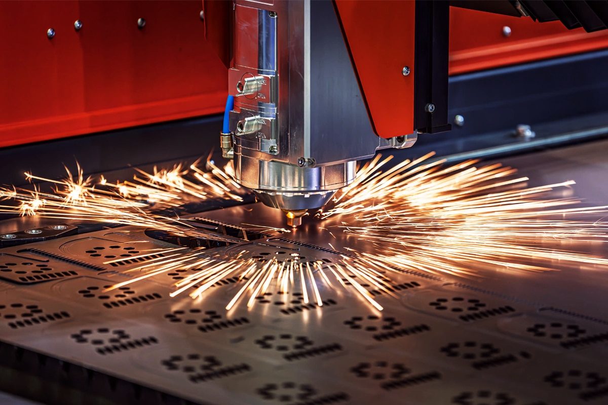
Laser Cutting Accuracy Guide
Laser cutting has become one of the most widely used manufacturing processes for producing metal and non-metal parts with complex shapes, narrow kerfs, smooth edges, and high dimensional consistency. However, the term laser cutting accuracy can mean different things depending on the material, machine configuration, part geometry, and application requirements. A machine may offer excellent positioning accuracy while the finished part still shows dimensional deviation caused by heat input, kerf variation, material movement, focus conditions, or incorrect cutting parameters. Understanding these factors is essential when evaluating whether laser cutting systems can meet a specific production tolerance.
Laser cutting accuracy generally describes how closely the dimensions and features of a finished part match the intended design. It is influenced by several related performance characteristics, including positioning accuracy, repeatability, dimensional accuracy, kerf width, edge quality, perpendicularity, and the ability to maintain consistent results over repeated production cycles. The achievable accuracy can also vary significantly between thin and thick materials, simple and complex geometries, and different laser technologies.
Modern fiber laser cutting machines can achieve very high levels of precision when the machine structure, motion system, laser source, cutting head, control system, and process parameters are properly matched. Nevertheless, simply choosing a high-power laser does not guarantee greater accuracy. Factors such as machine rigidity, servo performance, focus position, nozzle alignment, assist-gas pressure, cutting speed, material quality, thermal distortion, calibration, and maintenance can all affect the final result.
This laser cutting accuracy guide explains the key concepts used to evaluate cutting precision, the factors that influence accuracy, typical tolerances for different materials and applications, common causes of dimensional errors, and practical methods for improving cutting performance. Understanding these principles helps manufacturers select suitable equipment, establish realistic tolerance requirements, reduce rejected parts, and achieve more consistent production quality.
Table of Contents
Understanding Laser Cutting Accuracy
Laser cutting accuracy is not determined by a single measurement. It is the combined result of machine positioning capability, motion stability, laser-process control, material behavior, kerf formation, thermal effects, and part geometry. Laser cutting machines may have excellent mechanical accuracy but still produce parts outside the required tolerance if cutting parameters, material conditions, or thermal distortion are not properly controlled. For this reason, understanding laser cutting accuracy requires evaluating both the machine itself and the finished parts it produces.
Different applications also emphasize different aspects of accuracy. A decorative panel may mainly require accurate contours and clean edges, while a precision mechanical component may require tight dimensional tolerances, accurate hole locations, good circularity, and consistent feature-to-feature positioning. The following concepts provide a practical framework for evaluating laser cutting performance.
What Is Laser Cutting Accuracy
Laser cutting accuracy refers to how closely a laser-cut part matches the dimensions, geometry, and feature locations specified in the original design. It describes the machine’s ability to transform CAD data into a physical component while keeping dimensional deviations within acceptable limits.
Accuracy is affected by the entire cutting system. The machine frame, guide rails, servo motors, drives, cutting head, laser source, CNC controller, focusing system, assist gas, and cutting parameters can all influence the final result. Material thickness, flatness, surface condition, residual stress, and thermal expansion also contribute to dimensional variation.
Laser cutting accuracy should therefore be considered as a complete process characteristic rather than simply a specification listed on a machine datasheet. Manufacturers need to evaluate whether the actual finished parts consistently satisfy the tolerances required by the intended application.
Dimensional Accuracy
Dimensional accuracy describes how closely the measured dimensions of a finished part correspond to the dimensions defined in the CAD drawing. Typical dimensions include overall length, width, diameter, slot size, hole diameter, and the distance between individual features.
For example, if a drawing specifies a component width of 100.00 mm and the finished component measures 100.08 mm, the dimensional deviation is 0.08 mm. Whether this is acceptable depends on the specified tolerance.
Dimensional accuracy can be influenced by kerf compensation, cutting speed, laser power, focus position, thermal expansion, material thickness variation, and machine calibration. Larger parts can also accumulate greater dimensional errors because thermal effects and motion-system deviations may become more significant over longer travel distances.
Good dimensional accuracy requires both accurate machine motion and stable cutting conditions.
Positioning Accuracy
Positioning accuracy refers to the ability of the machine’s motion system to move the cutting head to a commanded position on the worktable. It is normally associated with the X- and Y-axis positioning performance of the CNC system.
When a controller commands the cutting head to move to a particular coordinate, positioning accuracy indicates how closely the actual position matches that coordinate. Errors can result from mechanical backlash, guide-rail deviations, servo-control errors, encoder limitations, thermal expansion, or machine-frame deformation.
Positioning accuracy is especially important for parts containing multiple holes, slots, cutouts, or other features that must be located precisely relative to one another. High positioning accuracy provides the mechanical foundation for producing accurate parts, but it does not guarantee finished-part accuracy by itself because the laser cutting process introduces additional variables.
Repeatability
Repeatability describes the machine’s ability to return to the same position or reproduce the same cutting result during repeated operations. A machine may have a small positioning offset but still demonstrate excellent repeatability if that offset remains consistent.
For production environments, repeatability is extremely important because manufacturers usually need hundreds or thousands of parts to remain within the same tolerance range. Poor repeatability can cause dimensions to fluctuate between parts even when the same cutting program and material are used.
Repeatability is influenced by servo performance, mechanical stability, machine temperature, guide-system condition, calibration, and process consistency. Stable laser output, gas pressure, nozzle condition, and focus position are also important for maintaining repeatable finished-part dimensions.
In many applications, excellent repeatability can be just as important as absolute positioning accuracy because consistent deviations can often be compensated through calibration or programming.
Contour Accuracy
Contour accuracy refers to how closely the actual cut path follows the intended shape defined by the CAD geometry. It is particularly important when producing curves, complex profiles, sharp corners, small radii, and irregular shapes.
Even when straight-line dimensions are accurate, contour errors can occur during rapid changes in direction. Machine acceleration, deceleration, servo response, interpolation performance, structural rigidity, and cutting speed all influence how accurately the cutting head follows complex paths.
Corners may become rounded, small radii may become distorted, or high-speed curves may deviate slightly from their programmed profiles. Advanced CNC systems compensate for these effects by controlling acceleration, velocity, and trajectory dynamically.
Contour accuracy becomes especially important for precision components, gears, brackets, decorative patterns, and parts that must fit closely with mating components.
Kerf Width and Kerf Consistency
Kerf width is the width of material removed by the laser during cutting. Because the laser beam removes a narrow strip of material rather than following an infinitely thin line, the CNC program must compensate for kerf width to achieve the intended final dimensions.
Kerf width varies depending on laser power, material type, material thickness, focus position, cutting speed, nozzle diameter, assist-gas pressure, and beam characteristics. If the kerf is wider or narrower than expected, the dimensions of the finished part can change.
Kerf consistency is equally important. A perfectly predictable kerf can be compensated for accurately, while a kerf that changes continuously along the cutting path can create dimensional inconsistencies.
Stable process parameters, correct focus settings, proper nozzle alignment, consistent material quality, and good cutting-head condition help maintain uniform kerf width throughout production.
Edge Squareness and Perpendicularity
Laser cutting accuracy also includes the geometry of the cut edge. Ideally, the cut surface should remain perpendicular to the top and bottom surfaces of the sheet. If the upper and lower edges do not align correctly, the cut may show taper or angular deviation.
This characteristic is commonly referred to as edge squareness or perpendicularity. It becomes increasingly important when cutting thick materials or producing components that must fit precisely during welding, assembly, or machining.
Poor perpendicularity may result from incorrect focus position, excessive cutting speed, unsuitable gas pressure, improper nozzle condition, beam misalignment, or unstable melt removal.
A component can have accurate top-surface dimensions while still having poor perpendicularity. Therefore, applications requiring tight three-dimensional fit or accurate edge geometry should evaluate both planar dimensions and cut-edge quality.
Hole Accuracy and Circularity
Small holes are often more difficult to cut accurately than large external contours. Hole accuracy involves both the final hole diameter and the geometric quality of the circular profile.
Circularity describes how closely the finished hole resembles a perfect circle. Poor machine dynamics, excessive cutting speed, incorrect piercing conditions, thermal accumulation, or an unsuitable hole-to-thickness ratio can cause holes to become slightly oval or irregular.
Hole diameter can also be affected by kerf width and heat input. Small holes are particularly sensitive because even a small dimensional deviation represents a significant percentage of the total diameter.
Optimized piercing strategies, reduced cutting speed, appropriate lead-in paths, stable beam delivery, and proper parameter settings can significantly improve hole quality. Precision applications may also require inspection of hole position, diameter, circularity, and taper.
Feature-to-Feature Accuracy
Feature-to-feature accuracy describes the positional relationship between different features on the same component. Examples include the distance between two holes, the position of a slot relative to an external edge, or the alignment between multiple cutouts.
This type of accuracy is especially important for parts that will be assembled using bolts, pins, tabs, locating features, or mating components. Even if every individual feature has the correct size, incorrect spacing between features can prevent proper assembly.
Feature-to-feature accuracy depends strongly on positioning accuracy, repeatability, machine calibration, and thermal stability. Sheet movement during cutting can also affect feature relationships, particularly when large quantities of material are removed from a part.
An effective cutting sequence can help minimize these problems by distributing heat and reducing material movement.
Accuracy Versus Precision
Although accuracy and precision are often used interchangeably, they describe different characteristics.
Accuracy describes how close a measured result is to the intended or target value. Precision describes how closely repeated measurements or results agree with one another.
For example, a machine that repeatedly produces a 100.20 mm part when the target dimension is 100.00 mm demonstrates good precision but poor accuracy. The results are consistent, but they are consistently incorrect. A properly calibrated machine should ideally provide both high accuracy and high precision.
This distinction is important when diagnosing laser cutting problems. Consistent dimensional offsets may indicate a calibration or kerf-compensation issue, while randomly varying dimensions may indicate poor repeatability, unstable process conditions, material movement, or mechanical problems.
Machine Accuracy Versus Finished-Part Accuracy
Machine accuracy and finished-part accuracy should not be treated as the same thing. Machine accuracy generally refers to the positioning and motion capabilities of the mechanical system under controlled conditions. Finished-part accuracy reflects the combined effects of machine performance and the actual laser cutting process.
A machine may have excellent positioning accuracy, but the resulting part can still deviate from the drawing because of kerf variation, thermal expansion, material stress, poor focus settings, incorrect gas pressure, sheet movement, or cutting-parameter errors.
Conversely, manufacturers can sometimes achieve very accurate parts by using calibration, kerf compensation, optimized cutting sequences, and process controls even when the machine’s theoretical positioning specification is not exceptionally high.
For this reason, machine specifications should be used as an important reference rather than the sole indicator of production capability. Actual sample cutting and dimensional inspection provide a more realistic assessment of whether laser cutting systems can satisfy a particular tolerance requirement.
Understanding laser cutting accuracy requires looking beyond a single tolerance specification. Finished-part accuracy is determined by dimensional accuracy, positioning accuracy, repeatability, contour control, kerf stability, edge perpendicularity, hole geometry, and the positional relationship between individual features. Each of these factors contributes to whether a laser-cut component matches its intended design.
It is also important to distinguish accuracy from precision. Accuracy indicates how closely a result matches the target dimension, while precision describes the consistency of repeated results. Reliable laser cutting requires both. Similarly, the positioning accuracy stated in a machine specification should not be confused with the dimensional accuracy that can actually be achieved on finished parts.
The final cutting result depends on the complete interaction between machine mechanics, CNC control, laser characteristics, cutting parameters, assist gas, material properties, thermal behavior, and cutting strategy. As tolerance requirements become tighter, controlling each of these variables becomes increasingly important.
By understanding the different components of laser cutting accuracy, manufacturers can establish realistic tolerance expectations, evaluate machines more effectively, diagnose dimensional problems, and select appropriate process settings for different applications. This foundation is essential for achieving consistent part quality while reducing rework, scrap, and unnecessary secondary machining.
How Accurate Are Laser Cutting Machines?
Modern laser cutting machines are capable of producing highly accurate parts, especially when cutting sheet metal under stable production conditions. However, there is no single accuracy value that applies to every laser cutting system. Actual performance depends on the laser type, machine structure, motion system, material, thickness, part geometry, cutting parameters, thermal conditions, and inspection method.
In general, modern industrial laser cutting machines can often achieve finished-part dimensional tolerances in the range of approximately ±0.05 mm to ±0.20 mm under favorable conditions, while high-end systems may achieve tighter results on suitable materials and geometries. Machine positioning specifications can be even tighter, but these specifications should not be confused with guaranteed finished-part tolerances. The real question is not simply how accurate laser cutting machines are, but how consistently they can maintain the required accuracy for a specific material, thickness, part size, and production volume.
Typical Accuracy of Modern Laser Cutting Machines
Modern CNC laser cutting machines are designed for high-precision production and can usually achieve much tighter tolerances than many conventional thermal cutting processes. For common sheet-metal applications, finished-part dimensional accuracy of approximately ±0.10 mm is often achievable with a well-maintained and properly calibrated machine. Depending on the machine class, material thickness, geometry, and process conditions, tolerances may range from around ±0.05 mm to ±0.20 mm or more.
High-end laser cutting systems with rigid frames, precision guide systems, high-resolution encoders, advanced servo controls, and optimized CNC compensation can produce even tighter results under controlled conditions. Small parts made from thin, flat sheet generally offer the best opportunity for achieving tight dimensional tolerances.
However, the achievable tolerance should always be matched to the application. A precision instrument component may require significantly tighter dimensional control than a structural bracket, enclosure panel, or decorative product.
Typical Repeatability Levels
Repeatability is generally better than absolute positioning accuracy because it measures how consistently the machine can reproduce the same movement or position. Many modern laser cutting machines offer repeatability specifications in the approximate range of ±0.02 mm to ±0.05 mm, although values vary by machine design and manufacturer.
High repeatability is extremely valuable in mass production. If a machine consistently reproduces the same dimensional result over hundreds or thousands of cycles, manufacturers can control production more effectively and compensate for predictable offsets when necessary.
Repeatability can deteriorate when guide rails are worn, servo systems are poorly tuned, machine temperature fluctuates significantly, optics become contaminated, or cutting parameters become unstable. Routine calibration and maintenance are therefore essential for maintaining long-term consistency.
Fiber Laser Cutting Accuracy
Fiber laser cutting machines are widely used for precision sheet-metal fabrication because they combine small focused spot sizes, excellent beam quality, fast motion systems, and highly responsive CNC controls.
When cutting thin and medium-thickness metals, a properly configured fiber laser cutting system can often achieve finished-part tolerances of approximately ±0.05 mm to ±0.15 mm under favorable conditions. Actual results depend heavily on machine quality, material, thickness, geometry, and process optimization.
Fiber lasers are particularly effective for cutting carbon steel, stainless steel, aluminum, brass, and copper. Their short wavelength allows efficient energy absorption by many metals and supports narrow kerfs and small heat-affected zones.
However, higher laser power does not automatically produce greater accuracy. Very high-power cutting can increase heat input, molten-material flow, and thermal effects if parameters are not properly controlled. Accuracy depends on the overall process rather than laser power alone.
CO2 Laser Cutting Accuracy
CO2 laser cutting systems can also provide high levels of accuracy and have been used for decades in precision manufacturing. Well-maintained industrial CO2 laser cutting systems can produce accurate parts with narrow kerfs and good edge quality, particularly when cutting suitable materials.
For metal cutting, dimensional tolerances may commonly fall around ±0.10 mm to ±0.20 mm depending on machine condition, material, thickness, and geometry. High-quality systems operating under optimized conditions may achieve tighter results.
CO2 lasers also have an important advantage in material versatility. They are widely used for cutting non-metal materials such as acrylic, wood, textiles, plastics, paper, leather, and composites.
Compared with fiber lasers, CO2 laser cutting systems normally contain a more complex beam-delivery path involving mirrors. The alignment, cleanliness, and condition of these optical components can influence beam quality and cutting accuracy. Regular optical inspection and maintenance are therefore especially important.
Nd and Other Laser Systems
Nd, Nd, disk lasers, and other solid-state laser technologies are used for specialized cutting and precision processing applications. Their achievable accuracy depends heavily on beam quality, pulse characteristics, machine configuration, and the intended processing method.
Nd lasers have historically been used for fine cutting, drilling, and applications requiring pulsed energy delivery. They can produce very small features when combined with appropriate optics and precision motion systems.
Disk lasers and other advanced solid-state systems can also provide excellent beam quality and high processing stability. In specialized precision manufacturing applications, these systems may achieve very tight tolerances.
However, fiber lasers have become more dominant in general industrial metal cutting because of their energy efficiency, high cutting speeds, relatively simple beam delivery, and reduced maintenance requirements. Other laser technologies remain important where specific wavelength, pulse, material, or process characteristics are required.
Sheet Laser Cutting Accuracy
Sheet laser cutting generally provides some of the highest accuracy available in thermal cutting because the material is relatively easy to support and the cutting process takes place primarily in two dimensions.
Flat sheets can be positioned securely on the cutting table, allowing the CNC motion system to control the cutting head precisely in the X and Y directions. When the material is flat and stable, dimensional deviations can be minimized.
Thin-sheet parts may achieve tolerances around ±0.05 mm to ±0.10 mm on high-quality equipment under controlled conditions. Larger components, thicker sheets, and parts with substantial thermal accumulation may require wider tolerances.
Sheet flatness is particularly important. Bowed or warped material changes the distance between the cutting head and the workpiece, which can influence focus conditions and kerf formation. Automatic height-control systems help compensate for moderate surface variation but cannot fully eliminate the effects of severely distorted material.
Tube Laser Cutting Accuracy
Tube laser cutting presents additional accuracy challenges compared with flat-sheet cutting. The workpiece must normally rotate while the cutting head moves along one or more linear axes, creating additional sources of positioning error.
Tube straightness, roundness, wall-thickness variation, clamping accuracy, chuck concentricity, rotation accuracy, and material deformation can all influence the finished result. Long tubes can also sag between support points, which may affect cutting position.
For many industrial tube laser applications, finished-part tolerances may commonly be around ±0.10 mm to ±0.30 mm depending on tube size, length, geometry, and machine quality. Higher-precision systems can achieve tighter results under suitable conditions.
Complex tube features such as intersecting holes, slots, bevels, and profiles require accurate coordination between linear and rotational axes. Advanced tube laser cutting machines use servo-controlled chucks, automatic centering, intelligent supports, and compensation software to improve accuracy.
Thin-Sheet Versus Thick-Plate Accuracy
Thin sheet generally allows greater cutting accuracy than thick plate. Several process factors explain this difference.
When cutting thin material, the laser can penetrate rapidly with relatively low heat input. The kerf is narrow, cutting speed is high, and the molten material can be removed efficiently. These conditions reduce thermal distortion and make kerf compensation more predictable.
As material thickness increases, the cutting process becomes more complex. More energy is required to penetrate the material, and molten metal must travel a greater distance through the kerf before being expelled. This can increase kerf width, taper, edge roughness, and sensitivity to changes in gas pressure and focus position.
Thick plate is also more susceptible to thermal distortion. Large parts containing multiple closely spaced cuts may accumulate significant heat, causing local expansion or movement during processing.
For these reasons, tolerance requirements should normally become more realistic as material thickness increases. A tolerance that is easily achievable in a 1 mm stainless steel sheet may be difficult or uneconomical to maintain in a 25 mm steel plate.
Why Manufacturer Specifications and Actual Cut Results May Differ
Laser cutting machine specifications often include values for positioning accuracy, repeatability, maximum acceleration, and other motion-system characteristics. These figures are useful for comparing machines, but they do not directly guarantee the accuracy of every finished part.
Manufacturer positioning specifications are typically measured under standardized test conditions. Actual production introduces many additional variables that are not fully represented by mechanical positioning tests.
Material thickness variation can affect kerf width and focus conditions. Sheet flatness can change the cutting-head distance. Residual stresses may cause parts to move after material is removed. Heat accumulation can create thermal expansion and distortion. Worn nozzles, contaminated protective lenses, incorrect focus positions, unstable gas pressure, or inappropriate cutting parameters can introduce additional errors.
Part geometry also matters. Large external profiles, small holes, narrow slots, sharp corners, and closely spaced features may respond differently even when cut on the same machine.
Environmental conditions can also influence accuracy. Temperature changes may cause expansion in machine components, while vibration or an unstable foundation can affect motion performance.
For this reason, the most reliable way to evaluate laser cutting accuracy is to perform sample cuts using the actual material, thickness, geometry, and production parameters expected in the application. Finished parts should then be measured using suitable inspection equipment.
Modern laser cutting machines are capable of very high accuracy, but achievable tolerances depend on much more than the machine’s published positioning specification. Under favorable conditions, high-quality industrial laser cutting systems can commonly produce sheet-metal parts within approximately ±0.05 mm to ±0.20 mm, while repeatability may be even tighter. Actual requirements and results vary considerably according to machine configuration and application.
Fiber lasers generally offer excellent accuracy for metal cutting because of their beam quality, narrow kerf, fast motion systems, and stable beam delivery. CO2 lasers can also provide high precision and remain especially useful for non-metal materials. Other laser technologies are used when specialized processing characteristics are required.
Material thickness and workpiece form have a major influence on achievable accuracy. Thin, flat sheet is generally easier to cut accurately than thick plate, while tube cutting introduces additional variables such as rotation, clamping, straightness, and workpiece support.
Most importantly, machine accuracy should never be treated as identical to finished-part accuracy. Published specifications describe the capabilities of the motion system under defined conditions, whereas actual cutting results reflect the combined effects of machine mechanics, laser processing, material behavior, thermal distortion, part geometry, maintenance, and parameter control. Manufacturers should therefore evaluate accuracy through real sample cutting and dimensional inspection whenever tight production tolerances are required.
Key Factors That Affect Laser Cutting Accuracy
Laser cutting accuracy is the result of many mechanical, optical, process, material, and operational factors working together. Even high-end laser cutting machines cannot consistently produce accurate parts if their motion system is poorly maintained, the cutting head is misaligned, the material is warped, or the cutting parameters are unsuitable. Likewise, excellent machine specifications do not automatically guarantee tight finished-part tolerances under every production condition.
The most important influences on accuracy can be grouped into machine structure, motion and transmission components, laser and cutting-head performance, assist-gas conditions, material characteristics, process parameters, thermal behavior, and operator control. Understanding these factors makes it easier to identify the source of dimensional errors and maintain consistent cutting quality over long production runs.
Machine Frame Rigidity
Machine frame rigidity provides the mechanical foundation for accurate laser cutting. During high-speed acceleration, deceleration, and directional changes, the cutting system generates dynamic forces that can cause vibration or deformation if the frame lacks sufficient stiffness.
A rigid machine bed helps maintain the geometric relationship between the guide rails, gantry, cutting head, and worktable. This is particularly important on high-speed fiber laser cutting machines, where rapid motion can place significant loads on the structure.
If the frame flexes during operation, the cutting head may deviate slightly from the programmed path. These deviations may be especially noticeable around corners, small-radius curves, and complex contours.
Frame design, material selection, welding quality, stress-relief treatment, machining accuracy, and long-term structural stability all affect rigidity. Heavy welded steel beds and cast machine structures are commonly used because they can provide good vibration resistance and dimensional stability.
Motion-System Accuracy
The motion system determines how accurately the cutting head follows the programmed toolpath. It includes the X- and Y-axis assemblies, servo motors, drives, guide rails, transmission components, encoders, and CNC control system.
Any positioning error in the motion system can directly influence feature locations and contour geometry. Backlash, axis misalignment, servo lag, transmission wear, and calibration errors can all reduce cutting accuracy.
Modern machines improve motion accuracy through closed-loop servo control, high-resolution feedback devices, precision linear guides, and advanced interpolation algorithms. These technologies help the cutting head maintain the commanded path even during high-speed changes in direction.
Motion-system accuracy becomes increasingly important when cutting small holes, narrow slots, fine details, and closely spaced features.
Guide Rails and Linear Bearings
Guide rails and linear bearings support and guide the movement of the cutting head and gantry. Their straightness, alignment, preload, lubrication, and wear condition have a direct effect on motion quality.
If guide rails are installed incorrectly or become worn, the cutting head may experience vibration, uneven resistance, or small positional deviations. Contamination from dust, metal particles, or insufficient lubrication can also accelerate wear.
High-quality linear guide systems provide smooth and predictable motion with minimal play. Correct installation is particularly important because even minor rail misalignment can affect the geometry of the entire machine.
Routine inspection, cleaning, and lubrication help preserve guide-system performance and prevent gradual accuracy loss.
Servo Motors and Drive Systems
Servo motors control the position, speed, and acceleration of the machine axes. Their responsiveness is critical for accurately following complex cutting paths.
When the cutting head enters a corner or changes direction rapidly, the servo system must adjust speed and position almost instantly. Poor servo tuning can create overshoot, lag, vibration, or contour deviation.
Modern servo drives use encoder feedback to continuously compare the commanded position with the actual axis position. The controller then makes rapid corrections to minimize error.
Servo performance is especially important for high-speed thin-sheet cutting, where the cutting head may undergo frequent acceleration and deceleration. Proper motor sizing, drive tuning, encoder resolution, and CNC coordination help maintain both accuracy and repeatability.
Gear Racks, Ball Screws, and Transmission Components
Transmission components transfer motion from the motors to the machine axes. Common systems include precision gear racks, pinions, ball screws, couplings, and gearboxes.
Gear racks are widely used on large-format laser cutting machines because they provide high travel speed and can cover long axis lengths. However, rack quality, tooth accuracy, installation alignment, lubrication, and backlash control influence positioning performance.
Ball screws are often used on smaller or highly precise motion systems because they can provide very accurate linear positioning. Their performance depends on lead accuracy, preload, bearing condition, and thermal stability.
Wear in couplings, reducers, gears, or mounting components can introduce backlash or uneven movement. Periodic inspection and adjustment are therefore important for maintaining long-term accuracy.
Laser Source Stability
Stable laser output helps maintain consistent kerf width, penetration, and edge quality. If laser power fluctuates during cutting, the amount of energy delivered to the material may change, causing variation in the cut.
Power instability can affect cutting speed capability, melt behavior, and kerf geometry. These effects may become more noticeable when operating close to the limits of a particular material thickness.
Modern fiber laser sources generally provide highly stable output, but system condition, cooling performance, optical components, and electrical supply can still influence consistency.
Maintaining the laser source according to the manufacturer’s requirements helps ensure that power and beam characteristics remain stable during production.
Cutting-Head Performance
The cutting head is responsible for focusing the laser beam and delivering assist gas to the cutting zone. Its condition and alignment directly influence the accuracy and quality of the cut.
A high-performance cutting head must maintain stable focus, accurate nozzle positioning, reliable height control, and consistent beam delivery. Internal contamination, damaged protective lenses, mechanical looseness, or sensor problems can reduce performance.
Automatic cutting heads often incorporate capacitive height sensing and motorized focus adjustment. These systems help maintain the correct relationship between the beam, nozzle, and material surface.
Because the cutting head operates close to molten metal, smoke, and spatter, regular inspection is essential.
Focus Control
The focus position determines where the laser beam reaches its smallest effective diameter relative to the material surface and thickness. Incorrect focus can change kerf width, edge quality, penetration, and cut taper.
The optimum focus position varies according to material type, material thickness, assist gas, laser power, and cutting strategy. Thin-sheet cutting may require a different focal position from thick-plate cutting.
If focus is positioned incorrectly, the upper and lower portions of the kerf may differ in width, resulting in poor edge perpendicularity or inaccurate dimensions.
Modern autofocus cutting heads can automatically adjust focal position for different materials and thicknesses. However, calibration remains important because an autofocus system with an incorrect zero reference can consistently produce poor results.
Nozzle Condition and Alignment
The nozzle directs assist gas into the kerf and must remain accurately centered relative to the laser beam. Even a small alignment error can create uneven gas flow and asymmetric cutting conditions.
A damaged, contaminated, or deformed nozzle may alter gas distribution and affect molten-material removal. This can produce uneven kerf width, excessive dross, poor edge quality, or dimensional variation.
Nozzle diameter must also match the material and cutting parameters. A nozzle that is too large or too small can affect gas velocity and pressure distribution.
Regular nozzle inspection, centering checks, and replacement are simple but important steps for maintaining accuracy.
Assist-Gas Pressure and Purity
Assist gas removes molten material from the kerf and influences oxidation, heat transfer, and edge formation. Common gases include oxygen, nitrogen, compressed air, and, in specialized applications, argon.
Incorrect gas pressure can cause incomplete melt removal, excessive dross, unstable cutting, or irregular kerf formation. Gas pressure that fluctuates during cutting can also produce inconsistent dimensions.
Gas purity matters as well. High-purity nitrogen is commonly used when clean, oxidation-free edges are required. Contamination can alter the chemical and thermal behavior of the cutting process.
Stable gas pressure, appropriate flow rate, clean supply lines, and correct gas purity help maintain predictable cutting conditions.
Material Properties
Material type has a major influence on achievable laser cutting accuracy. Thermal conductivity, reflectivity, melting temperature, surface condition, chemical composition, and internal stress all affect how the material reacts to laser energy.
Carbon steel, stainless steel, aluminum, copper, and brass behave differently during cutting. Parameters optimized for one material cannot simply be transferred to another without adjustment.
Material consistency is also important. Variations in alloy composition, coating thickness, surface contamination, or internal stress can cause differences between sheets from different suppliers or production batches.
For applications requiring tight tolerances, consistent material quality can be just as important as machine capability.
Sheet Flatness
Flatness directly affects the distance between the cutting head and the workpiece. Laser cutting systems normally use height-control sensors to maintain a specified nozzle gap, but severe sheet distortion can still create problems.
Warped sheet may cause the cutting head to continuously adjust its height, potentially affecting focus conditions and motion stability. In extreme cases, the nozzle may collide with raised sections of the material.
Sheet flatness can also affect finished-part dimensions. Residual stress in rolled or formed sheet may cause parts to distort after they are separated from the surrounding material.
Using high-quality flat material, effective sheet support, and appropriate cutting sequences can reduce these effects.
Cutting Parameters
Laser power, cutting speed, focus position, gas pressure, nozzle diameter, frequency, duty cycle, and lead-in settings all contribute to cutting accuracy.
Cutting too slowly may introduce excessive heat and widen the kerf. Cutting too quickly may produce incomplete penetration or unstable molten-material removal. Incorrect power settings can similarly change kerf geometry and edge quality.
Corner speeds often need to be reduced because the cutting head cannot maintain full straight-line velocity during sharp directional changes. Without proper control, excess heat can accumulate around corners and distort the geometry.
Well-developed process databases provide useful starting points, but fine adjustment may be required for specific materials, thicknesses, and tolerance requirements.
Thermal Effects
Laser cutting is a thermal process, so heat inevitably influences accuracy. The laser locally heats the material to melting or vaporization temperature, while surrounding areas remain cooler.
This temperature difference causes thermal expansion. As cutting continues, heat can accumulate in the sheet and cause temporary or permanent distortion.
Closely spaced cuts, dense perforation patterns, long continuous contours, and thick materials tend to generate greater thermal effects. Large parts can also experience dimensional movement as different regions heat and cool.
Cutting sequence optimization can help distribute heat more evenly. Strategies may include alternating between different areas of the sheet, cutting internal features before external contours, and allowing time for localized cooling when necessary.
Operator Setup and Process Control
Even highly automated laser cutting equipment depends on correct setup and process management. Operator decisions can strongly influence finished-part accuracy.
Before cutting, the operator should verify the correct material, thickness, program, nozzle, focus setting, gas type, pressure, and process parameters. Machine calibration and sheet positioning should also be checked.
During production, operators should monitor cut quality, nozzle condition, protective lenses, gas pressure, material behavior, and signs of thermal distortion. Unexpected changes should be investigated before large quantities of defective parts are produced.
Good process control also includes measuring sample parts at appropriate intervals. This allows dimensional trends to be identified early and corrections to be made before tolerances are exceeded.
Standardized procedures, trained operators, documented parameter libraries, preventive maintenance, and regular inspection all contribute to consistent cutting accuracy.
Laser cutting accuracy depends on the combined performance of the machine, laser cutting system, cutting process, material, and operator. Machine frame rigidity provides structural stability, while the motion system, guide rails, servo motors, and transmission components determine how accurately the cutting head follows the programmed path.
Laser source stability, cutting-head condition, focus control, nozzle alignment, and assist-gas performance influence how consistently the beam interacts with the material. Even small changes in these areas can alter kerf width, edge geometry, hole dimensions, and contour accuracy.
Material quality also plays a critical role. Sheet flatness, thermal properties, residual stress, thickness consistency, and surface condition can all affect the final dimensions of laser-cut components. Cutting parameters must therefore be optimized for each material and thickness rather than treated as universal settings.
Thermal effects deserve particular attention because heat accumulation can cause expansion and distortion even when the machine itself is operating accurately. Intelligent cutting sequences and stable process conditions help minimize these problems.
Ultimately, maintaining high laser cutting accuracy requires a complete process-control approach. A rigid and precisely calibrated machine must be combined with stable laser output, well-maintained components, suitable material, optimized parameters, and disciplined operator practices. Controlling all of these factors allows manufacturers to achieve tighter tolerances, improve repeatability, reduce scrap, and maintain consistent quality across long production runs.
How Laser Beam Characteristics Influence Accuracy
Laser cutting accuracy depends not only on the mechanical precision of the machine but also on the characteristics of the laser beam itself. The beam determines how energy is delivered into the material, how narrow the kerf can be, how stable the cutting process remains, and how consistently the programmed geometry is transferred to the workpiece. Even a highly accurate motion system can produce poor dimensional results if the beam is unstable, incorrectly focused, misaligned, or affected by contaminated optics.
Important beam-related factors include beam quality, diameter, focused spot size, focal length, focus position, depth of focus, energy distribution, power stability, alignment, and optical cleanliness. These factors interact closely. A small focused spot can improve fine-feature cutting, for example, but only if the focus position remains stable and the optical system is correctly aligned. Understanding these relationships helps manufacturers optimize cut quality and maintain tighter dimensional tolerances.
Laser Beam Quality
Laser beam quality describes how effectively laser beams can be focused into a small, well-defined spot. It is commonly associated with parameters such as the M² value, where a value closer to 1 indicates a beam that behaves more like an ideal Gaussian beam.
Better beam quality generally allows the laser to be focused more tightly, producing a smaller spot and higher power density. This can support narrower kerfs, sharper corners, smaller holes, and more precise contours.
Poorer beam quality produces a larger or less uniform focused spot. This can increase kerf width and reduce the ability to reproduce small geometric details accurately. It may also make the process more sensitive to focus position and material thickness.
Beam quality is therefore especially important in applications involving thin sheet, micro-features, small holes, narrow slots, or tight contour tolerances.
Beam Diameter
Beam diameter refers to the width of the laser beam before it is focused onto the workpiece. It influences the final focused spot size and the way the beam interacts with the focusing optics.
A larger input beam can often be focused into a smaller spot when used with suitable optics, resulting in higher energy density. However, the optical system must be designed to accommodate the beam correctly. An oversized or poorly controlled beam may be clipped by optical components, causing energy loss or distortion.
Beam diameter also affects the sensitivity of the system to alignment errors. If the beam does not pass centrally through the optical path, the energy distribution at the focus can become asymmetric.
Consistent beam diameter helps maintain stable focusing behavior and predictable kerf formation throughout production.
Focused Spot Size
Focused spot size is one of the most important beam characteristics affecting cutting accuracy. It represents the diameter of the laser beam at or near its smallest point after passing through the focusing lens.
A smaller focused spot creates higher power density and generally allows a narrower kerf. This improves the machine’s ability to cut fine details, small radii, narrow slots, and small-diameter holes.
However, an extremely small spot is not always advantageous. Smaller spots typically have a shorter depth of focus, meaning that performance can become more sensitive to material height variation and focus-position errors.
The ideal spot size therefore depends on the application. Thin-sheet precision cutting often benefits from a small spot, while thicker materials may require a balance between spot size, depth of focus, penetration stability, and kerf geometry.
Focal Length
Focal length is the distance over which the focusing optic brings the laser beam to its focal point. Different focal lengths produce different combinations of spot size and depth of focus.
Shorter focal lengths generally create smaller focused spots and higher power density. This is useful for thin materials and detailed cutting where narrow kerfs are important.
Longer focal lengths produce larger focused spots but offer a greater depth of focus. This can improve process stability when cutting thicker materials or when the workpiece surface is not perfectly flat.
The selected focal length therefore represents a trade-off between maximum precision and process tolerance. For very fine features, a short focal length may provide better geometric definition, while thicker-plate cutting may benefit from a longer focal length and broader focus range.
Focus Position
Focus position describes the location of the beam’s focal point relative to the material surface and thickness. It may be positioned at the top surface, inside the material, or below the surface depending on the cutting application.
Incorrect focus position can change the kerf width, taper, penetration behavior, and edge perpendicularity. For example, if the focus is too high or too low, the beam may produce an excessively wide kerf on one side of the material thickness.
The optimum focus position depends on the material, thickness, laser power, assist gas, and cutting strategy. Thin materials often require precise focus control because a small shift can noticeably affect kerf dimensions.
Modern autofocus cutting heads improve consistency by automatically adjusting focal position for different materials and thicknesses. However, correct calibration remains essential because an inaccurately referenced autofocus system can repeatedly produce dimensional errors.
Depth of Focus
Depth of focus refers to the range around the focal point within which the laser beam remains sufficiently concentrated for effective cutting.
A greater depth of focus makes the cutting process more tolerant of sheet unevenness, height variation, and minor focus-position errors. This is particularly useful for thick materials and large-format sheets.
A small focused spot generally has a shorter depth of focus. This offers excellent precision but makes the process more sensitive to material flatness and cutting-head height.
The relationship between spot size and depth of focus is therefore an important design consideration. High-precision thin-sheet cutting may prioritize a very small spot, while thick-plate processing may benefit from a longer depth of focus to maintain stable energy distribution through the material thickness.
Beam Mode and Energy Distribution
Beam mode describes how laser energy is distributed across the cross-section of the beam. The energy distribution can significantly influence kerf shape, melt behavior, and edge quality.
An ideal Gaussian-like beam concentrates more energy near the center, creating high central power density and supporting fine, precise cutting. Other beam profiles may distribute energy more evenly or in more complex patterns.
Modern laser cutting systems may use beam-shaping technologies to optimize energy distribution for different materials and thicknesses. Some cutting processes benefit from concentrated energy, while others perform better with a wider or ring-shaped distribution.
If the beam mode becomes unstable or asymmetric, the kerf may become uneven. This can create different cut widths on opposite sides of a contour, reduce circularity, and affect edge perpendicularity.
Stable and predictable energy distribution is therefore essential for maintaining consistent accuracy.
Laser Power Stability
Laser power stability determines how consistently the source delivers energy during cutting. Fluctuating power can change the amount of material melted or vaporized and therefore influence kerf width and penetration.
If power suddenly decreases, the cut may become incomplete or require slower motion. If power increases unexpectedly, the kerf may widen and excessive heat may be introduced into the material.
Small power variations can be particularly noticeable during precision cutting, where dimensional tolerances are tight, and kerf compensation depends on consistent process conditions.
Modern industrial laser sources are generally designed to provide stable output, but cooling problems, electrical instability, source aging, or optical contamination can affect performance.
Monitoring laser output and maintaining the cooling and electrical systems help preserve consistent power delivery.
Beam Alignment
Beam alignment ensures that the laser travels correctly through the optical system and remains centered relative to the focusing lens and nozzle.
If the beam is misaligned, it may not pass through the center of the nozzle. This can cause asymmetric kerf formation and uneven interaction between the beam and assist gas.
Misalignment may also create different cut conditions depending on the direction of travel. A part might appear accurate along one axis but show different kerf widths or edge quality when cutting in another direction.
Beam alignment is especially important in systems with more complex optical paths, such as traditional CO2 laser cutting machines. Fiber laser cutting systems have a simpler delivery path, but cutting-head alignment and nozzle centering are still critical.
Regular beam-centering checks help maintain symmetrical and predictable cutting conditions.
Effects of Optical Contamination on Accuracy
Optical contamination can gradually reduce laser cutting accuracy even when the machine’s mechanical components remain in excellent condition. Protective windows, lenses, mirrors, and other optical surfaces can become contaminated by smoke, dust, vapor, or cutting spatter.
Contamination absorbs or scatters part of the laser energy. This can reduce effective power at the workpiece and alter the shape or position of the focused beam.
A contaminated protective lens may also heat unevenly, creating thermal lensing. This phenomenon changes the optical properties of the component and can shift the focal position during operation.
As contamination becomes more severe, operators may notice wider kerfs, inconsistent penetration, poorer edge quality, increased dross, or changing dimensional results.
Regular inspection and replacement of protective optics are therefore important parts of accuracy maintenance. Clean optical components allow the beam to retain its intended shape, power density, and focal position.
Laser beam characteristics have a direct influence on how accurately laser cutting machines can transfer programmed geometry into a finished part. Beam quality, diameter, focused spot size, focal length, focus position, and depth of focus determine how concentrated the laser energy is and how consistently it interacts with the material.
A small, well-controlled focused spot can produce narrow kerfs and fine features, but it may also make the process more sensitive to focus errors and material flatness. Focal length and depth of focus must therefore be selected according to the material thickness and required level of precision.
Beam mode and energy distribution affect kerf symmetry, melt behavior, and edge geometry, while stable laser power is necessary for maintaining consistent cutting conditions. Proper beam alignment ensures that energy and assist gas remain centered on the programmed path.
Optical contamination can gradually degrade all of these characteristics by reducing power transmission, distorting the beam, or shifting the focal position. For this reason, regular inspection, cleaning, alignment, and calibration of the optical system are essential.
Maintaining stable beam characteristics allows manufacturers to achieve narrower kerfs, better contour definition, more accurate holes, improved edge perpendicularity, and more consistent dimensions across repeated production runs.
How Cutting Parameters Affect Accuracy
Laser cutting accuracy depends heavily on parameter selection. Even when the machine structure, motion system, laser source, and cutting head are capable of high precision, incorrect process settings can cause dimensional deviation, excessive kerf width, taper, rounded corners, distorted holes, or inconsistent edges. The key challenge is that cutting parameters do not work independently. Laser power, cutting speed, focus position, nozzle configuration, assist-gas conditions, pulse settings, piercing strategy, and motion control all interact with one another.
The most accurate results are usually achieved when sufficient energy is delivered to produce a stable cut without introducing unnecessary heat. At the same time, assist gas must remove molten material efficiently, the beam must remain properly focused, and the motion system must maintain the intended path through corners and detailed features. Parameter optimization is therefore a balancing process. Settings that maximize cutting speed are not always the same as those that maximize dimensional accuracy or edge quality.
Laser Power
Laser power determines how much energy is available to melt, burn, or vaporize the material during cutting. It directly influences penetration capability, cutting speed, kerf formation, and thermal input.
Insufficient laser power can produce incomplete penetration, unstable cuts, excessive dross, and irregular kerf edges. These defects can make the finished dimensions unpredictable. If power is too high for the material thickness and selected speed, excessive melting may enlarge the kerf and increase the heat-affected zone.
High power can be particularly problematic around small holes, corners, and narrow features because the cutting head moves more slowly in these areas, allowing additional heat to accumulate.
For maximum accuracy, laser power should be matched to material type, thickness, cutting speed, assist gas, and feature geometry rather than simply set as high as possible.
Cutting Speed
Cutting speed has a major influence on accuracy because it determines how long the laser interacts with each section of material.
If the cutting speed is too slow, excessive energy is deposited into the workpiece. This can widen the kerf, increase the heat-affected zone, round sharp corners, and cause thermal distortion.
If speed is too high, the laser may not fully penetrate the material or may leave an unstable cut edge. Incomplete molten-material removal can result in dross and irregular dimensions.
The optimum speed produces stable penetration with minimum unnecessary heat input. Thin-sheet cutting generally allows much higher speeds than thick-plate cutting, while small holes and complex contours often require lower speeds than long straight cuts.
Focus Position
Focus position controls where the laser beam reaches its highest energy density relative to the material surface. A small change in focus can significantly affect kerf width, edge taper, and penetration behavior.
Incorrect focus may cause the upper and lower edges of the cut to have different widths. This reduces perpendicularity and may cause the measured dimension to vary depending on where the part is inspected.
The optimum focus position varies according to material type, thickness, laser power, assist gas, and cutting mode. For some applications, the focus is placed near the material surface, while other processes perform better with the focus inside or below the material.
Accurate focus calibration is especially important when producing precision parts because incorrect focus can introduce consistent dimensional error throughout an entire production batch.
Nozzle Height
Nozzle height refers to the distance between the nozzle tip and the workpiece surface. This gap influences assist-gas flow, pressure distribution, and process stability.
If the nozzle is positioned too far from the material, gas flow may disperse before reaching the kerf. This can reduce molten-material removal efficiency and lead to dross or irregular cut edges.
If the nozzle is too close, there is a greater risk of collision with warped sheet, slag, or raised features. An excessively small gap can also disturb gas-flow characteristics.
Modern cutting machines use capacitive height-control systems to maintain a consistent nozzle-to-workpiece distance. Accurate height sensing becomes particularly important when cutting warped material or large sheets with changing surface elevation.
Nozzle Diameter
Nozzle diameter affects the volume, velocity, and distribution of assist gas entering the cutting zone.
A nozzle that is too small may restrict gas flow and reduce the ability to remove molten material, particularly when cutting thicker plate. A nozzle that is too large may reduce gas efficiency or create a less concentrated flow pattern.
The correct nozzle diameter depends on material thickness, gas type, pressure, laser power, and cutting strategy. Thin-sheet precision cutting often uses smaller nozzle openings, while thicker materials may require larger diameters.
Nozzle selection also affects kerf consistency. When gas delivery is stable and symmetrical, molten material is expelled more uniformly, helping maintain predictable cut dimensions.
Assist-Gas Type
Assist-gas type changes the thermal and chemical behavior of the cutting process. Oxygen, nitrogen, compressed air, and occasionally argon are used depending on the material and desired edge condition.
Oxygen reacts with carbon steel and adds additional heat through oxidation. This allows efficient cutting of thicker steel but may increase thermal effects and influence kerf width.
Nitrogen is commonly used for stainless steel, aluminum, and applications requiring oxidation-free edges. Because nitrogen primarily removes molten material rather than contributing significant chemical heat, it can provide clean and controllable cutting conditions.
Compressed air offers an economical alternative for many applications but may produce different edge characteristics because it contains both oxygen and nitrogen.
The selected gas should support stable kerf formation and consistent melt removal if dimensional accuracy is a priority.
Assist-Gas Pressure
Assist-gas pressure directly affects how efficiently molten material is removed from the kerf.
Pressure that is too low may leave molten metal inside or beneath the cut, causing dross, rough edges, and inconsistent kerf geometry. Pressure that is too high can disturb the molten zone, increase turbulence, or create unnecessary gas consumption without improving accuracy.
The optimum pressure varies significantly depending on gas type, nozzle diameter, material thickness, and cutting speed. Nitrogen cutting often requires relatively high pressure, while oxygen cutting typically operates at lower pressure because oxidation assists the cutting process.
Stable pressure is as important as the absolute pressure value. Fluctuations can cause changing kerf conditions during a single cut and reduce dimensional consistency.
Pulse Frequency and Duty Cycle
Pulse frequency and duty cycle are particularly important when the laser operates in pulsed mode. These parameters control how frequently energy pulses are delivered and how long the laser remains active during each cycle.
High-frequency pulsing can create smoother and more continuous energy delivery, while lower frequencies may reduce average heat input and improve control in certain precision applications.
Duty cycle determines the proportion of time the laser is emitting energy. Increasing duty cycle raises average energy input, while reducing it can limit overheating.
Pulsed parameters are especially useful for cutting small holes, thin materials, delicate features, or heat-sensitive components. Incorrect frequency or duty cycle can cause uneven penetration, excessive heat, rough edges, or dimensional variation.
The optimum combination depends on material properties and feature geometry.
Piercing Parameters
Piercing is often one of the most thermally aggressive parts of the laser cutting process. The laser must create an initial hole before contour cutting begins, and poorly controlled piercing can damage surrounding material.
Excessive piercing power or duration can create a large molten area, excessive spatter, or a crater around the starting point. This may affect nearby features or distort the beginning of the contour.
Piercing too quickly may result in incomplete penetration, causing instability when cutting starts.
Modern laser cutting systems use techniques such as staged piercing, pulse piercing, controlled focus changes, and pressure adjustments to reduce heat and spatter.
Piercing should also be positioned appropriately relative to the finished contour. When possible, the pierce point is placed outside the final part geometry using a lead-in path so that any local damage does not affect the finished edge.
Acceleration and Deceleration
Acceleration and deceleration control how quickly the cutting head changes speed. These settings have a major influence on contour accuracy during high-speed cutting.
The cutting head can travel rapidly along straight sections, but it must slow down when approaching tight corners, small radii, or abrupt changes in direction. If acceleration values are too aggressive for the machine’s mechanical capability, overshoot, vibration, or path deviation may occur.
If acceleration is too conservative, productivity may decrease unnecessarily and extra heat may accumulate because the cutting head spends more time in certain areas.
The best settings balance motion speed with the dynamic capability of the machine frame, gantry, servo system, and transmission components.
Corner-Speed Control
Corners are particularly sensitive to cutting-speed changes because the cutting head cannot instantly change direction while maintaining full linear speed.
Without corner-speed control, the machine may overshoot the programmed path or produce rounded corners. However, simply reducing speed can create another problem: increased local heat input. If laser power remains unchanged while the machine slows significantly, the corner may melt excessively and become enlarged.
Modern CNC systems coordinate speed reduction with laser power modulation. This helps maintain a more consistent energy input per unit length.
Correct corner-speed control improves sharpness, reduces burning, and helps preserve dimensional accuracy in complex geometries.
Lead-In and Lead-Out Settings
Lead-in and lead-out paths control how the cutting head enters and exits the actual part contour.
Starting directly on the finished edge can leave a visible mark, crater, or dimensional irregularity caused by piercing and acceleration. A lead-in allows the piercing and stabilization process to occur away from the final contour before the cutting head transitions smoothly onto the programmed edge.
Lead-out paths can similarly prevent end-of-cut defects where the laser finishes the contour.
The length, shape, angle, and location of lead-ins and lead-outs should be selected according to part geometry. Straight, arc, and tangent approaches are commonly used.
Poorly positioned lead-ins may interfere with nearby features or create localized heat accumulation. Properly designed lead strategies can significantly improve edge consistency and contour accuracy.
Parameter Optimization for Maximum Accuracy
Maximum accuracy is achieved by optimizing the complete group of cutting parameters rather than adjusting individual settings in isolation.
A practical optimization process begins with a proven parameter set for the specific material and thickness. Test cuts can then be used to evaluate dimensional accuracy, kerf width, edge perpendicularity, dross, hole quality, and thermal distortion.
Adjustments should be made systematically. For example, if the kerf is too wide, the solution may involve increasing cutting speed, reducing power, changing focus position, or improving gas delivery. Changing several variables at once makes it difficult to identify the real cause.
Different features may also require different parameter strategies. Large external contours can often be cut at high speed, while small holes, sharp corners, narrow slots, and closely spaced details may need reduced power or specialized motion settings.
Modern CNC systems can automatically apply feature-specific parameters, such as lower power for small circles, reduced corner speeds, optimized piercing cycles, and dynamic focus control.
For demanding applications, the best parameter set should be validated by measuring finished parts rather than relying only on visual edge quality.
Cutting parameters have a direct and significant effect on laser cutting accuracy. Laser power and cutting speed determine how much energy enters the material, while focus position, nozzle height, and nozzle diameter influence beam interaction and assist-gas delivery. Assist-gas type and pressure affect molten-material removal, oxidation, kerf stability, and edge quality.
Pulse frequency, duty cycle, and piercing parameters become particularly important when producing small or heat-sensitive features. Motion-related settings such as acceleration, deceleration, and corner-speed control determine how accurately the cutting head follows complex geometries without introducing overshoot or excessive local heating. Lead-in and lead-out strategies help keep piercing defects and transition marks away from critical finished edges.
No single parameter can guarantee high accuracy. Changing one setting often affects several other aspects of the process, so optimization must consider the complete interaction between laser energy, machine motion, gas flow, material behavior, and part geometry.
The most reliable approach is to begin with validated material-specific parameters, conduct controlled test cuts, measure the resulting parts, and make systematic adjustments. Combining accurate machine motion with well-optimized cutting parameters allows manufacturers to achieve narrower and more consistent kerfs, sharper features, better edge perpendicularity, reduced thermal distortion, and more repeatable finished-part dimensions.
Material-Related Factors Affecting Laser Cutting Accuracy
Material characteristics play a major role in determining the accuracy that can be achieved with laser cutting. Even when the same machine, cutting head, laser source, and motion system are used, different materials can produce noticeably different dimensional results. This is because each material responds differently to laser energy, heat accumulation, melting, oxidation, assist gas, and mechanical stress.
Material type, thickness, composition, reflectivity, thermal conductivity, surface condition, flatness, and thickness tolerance all influence kerf formation and dimensional stability. Protective films and coatings can also change the way the beam interacts with the workpiece. In addition, internal stresses may cause parts to move or distort after they are separated from the surrounding sheet. For tight-tolerance production, understanding these material-related effects is just as important as selecting a high-precision machine.
Material Type
Different materials absorb laser energy in different ways and have different melting temperatures, thermal properties, and chemical reactions with assist gases. These differences directly affect kerf width, cutting speed, heat input, and edge quality.
For example, carbon steel can be cut efficiently with oxygen because the oxidation reaction adds heat to the process. Stainless steel is often cut with nitrogen to produce clean, oxide-free edges. Aluminum transfers heat quickly, while copper and brass combine high thermal conductivity with high reflectivity.
Because of these differences, each material requires its own parameter set. A machine that produces excellent dimensional accuracy on mild steel may require significantly different power, speed, focus, and gas settings to achieve comparable results on aluminum or copper.
Material Thickness
Material thickness is one of the strongest influences on laser cutting accuracy. Thin sheet generally allows narrower kerfs, higher cutting speeds, and lower overall heat input, making tight tolerances easier to achieve.
As thickness increases, the laser must deliver more energy to penetrate the material. Cutting speeds decrease, kerf width may increase, and molten material must travel farther before leaving the cut. These conditions can increase taper, dross, heat accumulation, and dimensional variation.
Thicker materials are also more sensitive to focus position and assist-gas performance. Small changes in focus or gas pressure may have a greater effect on the lower portion of the cut.
For this reason, realistic tolerance requirements often become wider as material thickness increases.
Material Composition
The chemical composition of a material affects its melting behavior, oxidation response, thermal conductivity, and absorption of laser energy.
Two sheets sold under the same general material category may behave differently if their alloy composition varies. Different grades of stainless steel, for example, can have different nickel, chromium, and molybdenum contents, while aluminum alloys may vary considerably in magnesium, silicon, or copper content.
These variations can influence cutting speed, edge quality, and kerf stability. In carbon steel, differences in carbon content and surface scale may also affect oxygen cutting behavior.
For precision applications, consistent material grade and supplier quality help reduce variation between production batches.
Surface Condition
The condition of the material surface affects how the laser beam is absorbed and how stable the cutting process remains.
Rust, scale, oil, paint, dirt, oxidation, scratches, or other contamination can change energy absorption and interfere with piercing or cutting. Surface irregularities may also alter the way assist gas flows around the cut.
Highly inconsistent surfaces can cause localized changes in kerf width or penetration. Heavy mill scale on carbon steel, for example, may make initial beam interaction less predictable.
Clean and consistent material surfaces generally provide better repeatability. When tight tolerances are required, material preparation may include cleaning, degreasing, or removing loose contaminants before cutting.
Reflectivity
Reflectivity determines how much laser energy is reflected rather than absorbed by the material surface.
Highly reflective metals such as copper, brass, and aluminum can reflect a significant portion of incident laser energy, particularly during the initial stages of cutting. This reduces effective energy absorption and can make piercing or process stabilization more difficult.
Fiber lasers are well suited to many reflective metals because their shorter wavelength is absorbed more efficiently than the wavelength of traditional CO2 lasers. Nevertheless, reflective materials still require appropriate process control.
Unstable absorption can produce inconsistent melt behavior, especially during piercing. Proper parameter selection and laser cutting systems designed for reflective materials help maintain dimensional accuracy.
Thermal Conductivity
Thermal conductivity describes how quickly heat spreads through a material. It has a direct effect on the size and stability of the molten zone.
Materials with high thermal conductivity, such as aluminum and copper, carry heat away from the cutting area rapidly. This means more laser energy may be required to maintain a stable cut.
If heat is removed too quickly, penetration can become unstable. On the other hand, once sufficient energy is applied, heat may spread into a larger surrounding region and influence thermal expansion.
Materials with lower thermal conductivity retain more heat close to the cutting zone. This can support efficient cutting but may increase localized heat accumulation.
Understanding thermal conductivity helps determine appropriate power, speed, and cutting strategy.
Sheet Flatness and Internal Stress
Sheet flatness is critical because the cutting head must maintain a consistent distance from the workpiece surface.
If the sheet is bowed, twisted, or locally raised, the nozzle-to-material distance can change continuously. Automatic height-control systems can compensate for moderate variation, but severe distortion may cause focus changes, unstable gas flow, or even nozzle collisions.
Internal stress creates a different problem. Rolled, formed, welded, or heat-treated material may contain residual stresses that are released when the laser separates parts from the sheet.
A part can therefore change shape after cutting even if the machine followed the programmed path accurately. Long narrow parts, asymmetric shapes, and components with large areas of material removed are especially susceptible.
Optimized nesting and cutting sequences can reduce distortion caused by residual stress.
Material Thickness Tolerance
Nominal material thickness and actual thickness are not always identical. Commercial sheet and plate are manufactured within defined thickness tolerances, so different areas or batches may vary slightly.
Thickness variation changes the amount of material the laser must penetrate. This can affect required energy, focus conditions, gas flow, and kerf geometry.
For ordinary fabrication, small thickness differences may have little practical effect. However, in tight-tolerance applications, variations can influence edge taper and the effective dimensions of the finished part.
Consistent material thickness helps make process parameters more predictable. Manufacturers producing precision components may therefore need tighter raw-material specifications rather than relying only on nominal thickness.
Protective Films and Surface Coatings
Many stainless steel, aluminum, and decorative sheets are supplied with protective films to prevent scratches during handling and fabrication. Other materials may have paint, galvanizing, anodizing, plating, or specialized coatings.
These surface layers can affect laser absorption, piercing, smoke generation, and edge quality. Some protective films are designed to remain in place during laser cutting, while others should be removed before processing.
If a film melts, burns, or lifts during cutting, it can contaminate the nozzle or protective lens. Coatings can also introduce additional heat or chemical reactions.
For accurate production, cutting parameters should be developed with the actual coated or film-covered material rather than assuming that bare-material settings will produce identical results.
Mild Steel
Mild steel is one of the most common materials used in laser cutting and can generally be processed with high accuracy.
Thin mild steel is often cut with nitrogen, compressed air, or oxygen depending on edge-quality and productivity requirements. Thicker steel is frequently cut with oxygen because the exothermic oxidation reaction contributes additional energy.
Oxygen cutting is highly efficient, but the chemical reaction can widen the kerf if parameters are not properly controlled. Excessive oxygen pressure or incorrect cutting speed may also affect edge shape.
Mild steel can contain mill scale or residual stress, both of which may influence repeatability. Clean, flat sheet with consistent thickness provides the best conditions for accurate cutting.
Stainless Steel
Stainless steel is well suited to high-precision laser cutting, especially when processed with high-pressure nitrogen.
Nitrogen prevents significant oxidation of the cut edge and helps produce clean, bright surfaces that often require little secondary finishing. Thin stainless steel can usually be cut with narrow kerfs and excellent dimensional consistency.
However, excessive heat can discolor or distort thin material. Small features and closely spaced cuts may require careful power and speed control.
Different stainless steel grades can also behave slightly differently because of variations in alloy content and thermal properties. Consistent material quality and optimized nitrogen pressure contribute to predictable results.
Aluminum
Aluminum can be cut accurately with modern fiber laser cutting systems, but its physical characteristics create additional challenges.
It has relatively high reflectivity and high thermal conductivity, which means part of the laser energy is reflected while absorbed heat spreads quickly away from the cutting zone. Higher energy density and carefully optimized parameters may therefore be required.
Thin aluminum can usually be cut very precisely, but heat-related distortion can become a concern because aluminum has a relatively high coefficient of thermal expansion.
Sheet quality also matters. Soft or thin aluminum sheets may deform easily during handling or cutting, affecting flatness.
Proper support, stable high-pressure assist gas, and controlled heat input help improve accuracy.
Copper and Brass
Copper and brass are among the more challenging metals for laser cutting because they are highly reflective and highly thermally conductive.
Modern fiber lasers have made cutting these materials much more practical, especially when the laser source and cutting head include protection against reflected energy.
During piercing, unstable absorption can affect hole quality and create local dimensional variation. Once the process stabilizes, however, accurate cutting is possible with suitable power, speed, focus, and gas settings.
Copper transfers heat extremely quickly, while brass behaves somewhat differently because of its zinc content. Each material therefore requires dedicated cutting parameters.
Good beam quality, stable focus, and clean optics are especially important when processing these materials.
Nonmetallic Materials
Laser cutting is also widely used for nonmetallic materials, including acrylic, wood, plywood, textiles, leather, rubber, paper, foam, and certain plastics and composites.
Accuracy on nonmetallic materials depends heavily on how the material responds to heat. Acrylic can produce clean and precise edges, while wood may char or vary in cutting behavior because of changes in density, grain, resin content, and moisture.
Textiles and foams may deform or move if they are not held securely. Some plastics can melt and produce a wider effective kerf than expected.
Material thickness consistency is often less predictable in natural and flexible materials than in metal sheet. This can make tight dimensional control more difficult.
Laser type is also important. CO2 lasers are commonly used for many nonmetal materials because their wavelength is efficiently absorbed by organic materials and plastics.
Why the Same Machine Produces Different Accuracy on Different Materials
Laser cutting machines do not interact with every material in the same way. Even when mechanical positioning accuracy remains unchanged, finished-part dimensions can vary because the cutting process changes.
Different materials absorb laser energy differently, conduct heat at different rates, melt at different temperatures, and react differently with assist gases. These characteristics influence kerf width, cutting speed, edge taper, thermal expansion, and distortion.
Thickness and surface condition add further variation. A thin stainless steel sheet may allow fast, narrow-kerf cutting with minimal heat input, while a thick aluminum plate may require more energy and produce greater thermal effects.
Material stress can also cause finished parts to move after cutting, creating dimensional differences that are unrelated to the machine’s axis accuracy.
Therefore, finished-part accuracy should always be evaluated under the actual material and thickness conditions expected in production.
Material characteristics are a fundamental part of laser cutting accuracy. Material type, thickness, composition, surface condition, reflectivity, and thermal conductivity determine how efficiently laser energy is absorbed and how the molten material behaves during cutting. These properties directly influence kerf width, edge quality, penetration stability, and dimensional consistency.
Physical characteristics are equally important. Sheet flatness affects nozzle height and focus stability, while internal stresses may cause components to deform after they are released from the surrounding sheet. Raw-material thickness tolerance can also introduce process variation, particularly in demanding applications. Protective films, galvanizing, paint, and other coatings can further change the way the laser interacts with the surface.
Mild steel, stainless steel, aluminum, copper, brass, and nonmetallic materials each require different cutting strategies. Some materials can be processed with narrow kerfs and minimal thermal effects, while others require greater energy input or more careful management of reflection and heat transfer.
This explains why single laser cutting machines do not provide identical finished-part accuracy on every material. Mechanical capability remains the same, but the cutting process itself changes. For reliable precision, parameters and tolerance expectations should therefore be developed specifically for the actual material, grade, thickness, surface condition, and application.
Kerf Width, Taper, and Dimensional Compensation
Laser cutting does not separate material along an infinitely thin line. As the focused laser beam moves through the workpiece, it melts, burns, or vaporizes a narrow path of material known as the kerf. The width and geometry of this kerf directly affect the final dimensions of the part. Without appropriate compensation, external profiles can become undersized, holes can become oversized, and mating features may fail to meet their specified tolerances.
Kerf behavior is influenced by the laser beam, material thickness, cutting speed, power, focus position, assist gas, nozzle condition, and other process variables. The kerf may also be slightly wider at one surface than the other, producing taper. Modern CNC laser cutting software compensates for these effects by offsetting the actual beam path from the nominal CAD contour. Accurate compensation requires a stable cutting process and properly calibrated kerf values for each material and thickness.
What Is Laser Cutting Kerf
Laser cutting kerf is the narrow gap created when the laser removes material along the programmed cutting path. Its width represents the amount of material lost during the cutting process.
For example, if a laser follows the exact centerline of a 100 mm square without compensation, the finished component will not necessarily measure exactly 100 mm. Because the beam removes material on both sides of its path, the final dimensions depend on whether the desired geometry is an internal or external contour.
Laser kerfs are generally much narrower than those produced by many conventional thermal cutting processes. This narrow kerf is one reason laser cutting can produce closely spaced features, detailed contours, and high material utilization. However, even a small kerf becomes important when tolerances are tight.
Factors That Determine Kerf Width
Kerf width is determined by the interaction of the laser beam, material, and cutting parameters. Focused spot size is one of the primary influences because it determines how concentrated the laser energy is at the workpiece.
Laser power and cutting speed also affect kerf formation. Excessive energy input may enlarge the molten region and produce a wider kerf, while excessive speed can result in incomplete or unstable cutting.
Focus position influences the beam diameter at different depths through the material. Assist-gas type, pressure, and nozzle diameter affect how molten material is expelled from the cut. Material properties such as melting temperature, thermal conductivity, reflectivity, and thickness further influence the resulting width.
Nozzle alignment, beam quality, optical condition, and cutting-head height must also remain stable. Consequently, kerf width should be treated as a process result rather than a fixed characteristic of the machine.
Kerf Width Versus Material Thickness
Material thickness has a significant influence on kerf width. Thin sheet can generally be cut with a small focused spot, high speed, and relatively low total heat input, allowing a narrow and well-defined kerf.
As thickness increases, the laser must maintain sufficient energy through a greater depth of material. Cutting speeds usually decrease, and the beam naturally changes diameter as it passes above and below its focal point. More molten material must also be removed through the kerf.
As a result, thicker materials often produce wider kerfs and greater differences between the upper and lower kerf dimensions. However, the relationship is not simply linear. Laser type, power, focus position, material, assist gas, and cutting strategy can substantially change the result.
Kerf values should therefore be established for individual combinations of material type and thickness rather than estimated from thickness alone.
Kerf Variation During Cutting
An ideal laser cutting process would maintain the same kerf width throughout every contour. In actual production, small variations can occur.
Acceleration and deceleration can change the amount of energy deposited per unit length. When the cutting head slows at corners, for example, local heat input can increase unless laser power is adjusted accordingly.
Material inconsistency can also cause kerf variation. Changes in thickness, surface condition, composition, or flatness may alter energy absorption and melt removal. Gas-pressure fluctuations, nozzle contamination, focus drift, or deteriorating protective optics can introduce additional variation.
Kerf consistency is often more important than simply achieving the smallest possible kerf. A slightly wider but highly stable kerf can be accurately compensated, while an unpredictable kerf makes tight dimensional control much more difficult.
Kerf Taper
Kerf taper occurs when the cut width is not uniform through the full material thickness. Instead of producing two perfectly parallel cut surfaces, the laser creates a slightly angled edge.
The kerf may be wider at the top and narrower at the bottom, or the opposite may occur depending on focus position and process conditions. This creates a difference between dimensions measured on the upper and lower surfaces of the finished component.
Taper is influenced by material thickness, focus position, beam characteristics, cutting speed, laser power, and assist-gas flow. It generally becomes more significant as material thickness increases.
Excessive taper can cause problems for parts that require precise edge perpendicularity, close-fitting assemblies, or accurate holes through the entire thickness.
Why the Top and Bottom Dimensions Can Differ
The focused laser beam does not maintain the same diameter throughout the complete thickness of the material. It converges toward the focal point and then diverges after passing through it. As a result, the energy distribution and effective kerf width can vary through the cut depth.
Molten-material behavior also contributes to this difference. Assist gas must push molten material downward through the kerf, and the interaction between gas flow, heat, and liquid metal changes from the top surface to the bottom.
If the resulting cut edges are tapered, an external part may measure slightly differently at its upper and lower surfaces. The same issue applies to holes and internal profiles.
For applications with strict dimensional or perpendicularity requirements, measurements should therefore specify where dimensions are evaluated rather than relying on a single unspecified surface measurement.
Internal Versus External Contour Compensation
Kerf compensation must account for whether the programmed geometry is an external profile or an internal feature.
For an external contour, the laser path is generally offset outward from the nominal finished-part boundary. This prevents the kerf from removing material from inside the required component dimension.
For an internal contour, such as a hole or cutout, the laser path is offset inward toward the material being removed. Otherwise, the resulting opening would become larger than the specified dimension.
The basic compensation amount is commonly related to approximately half of the effective kerf width because the programmed beam centerline must be shifted by the distance between the beam path and the intended finished edge.
Correctly identifying internal and external contours is therefore essential for accurate CNC programming.
Kerf Compensation in CNC Software
Modern laser cutting software can automatically apply kerf compensation to programmed contours. The operator or process database specifies an appropriate compensation value, and the software offsets the cutting path accordingly.
This allows the original CAD geometry to remain at its nominal dimensions while the CAM or CNC system calculates the actual trajectory required for the laser beam.
Advanced systems can store different compensation values for different materials, thicknesses, gases, nozzles, and cutting processes. They may also apply different settings to external contours, holes, and specialized features.
However, software compensation can only correct predictable dimensional offsets. It cannot fully compensate for unstable kerf width, severe thermal distortion, material movement, mechanical positioning errors, or inconsistent cutting conditions.
Calibrating Kerf Compensation
Accurate kerf compensation should be based on actual cutting results rather than assumptions. Calibration normally begins by selecting the material, thickness, gas, nozzle, focus, and cutting parameters that will be used in production.
A test piece with known external and internal dimensions is then cut and allowed to cool before measurement. Precision measuring equipment can be used to compare the finished dimensions with the nominal CAD values.
If external dimensions are consistently too small or too large, the contour offset can be adjusted accordingly. Internal features should be evaluated separately because hole and slot behavior may differ from large external profiles.
Several samples should ideally be measured to distinguish a consistent compensation error from random process variation. Once a stable value has been established, it can be stored in the machine’s process database for future production.
Calibration should be repeated when significant variables change, such as material thickness, nozzle size, gas type, focus conditions, or cutting strategy.
Preventing Overcompensation and Undersized Features
More kerf compensation does not necessarily produce greater accuracy. If the compensation value is excessive, external contours may become oversized while internal features become undersized. Too little compensation creates the opposite result.
Undersized holes and slots are particularly important because they can prevent bolts, tabs, bearings, or mating components from fitting correctly. Small features are also more sensitive to thermal effects and motion dynamics, meaning that a compensation value developed from a large external contour may not always provide the best result for small holes.
To prevent overcompensation, adjustments should be based on measured dimensional deviations rather than visual inspection alone. Changes should be made incrementally, followed by additional test cuts.
Measurements should also be performed after the component has cooled to a stable temperature because thermal expansion immediately after cutting can produce misleading results.
For high-precision applications, manufacturers may use feature-specific compensation values or specialized small-hole parameters rather than applying one universal offset to every contour.
Kerf width, taper, and dimensional compensation are fundamental considerations when producing accurate laser-cut components. Because laser cutting physically removes a narrow path of material, the centerline followed by the laser beam cannot always correspond directly to the nominal finished-part boundary. The cutting path must be offset to account for the material removed by the kerf.
Kerf width depends on beam characteristics, material type and thickness, laser power, cutting speed, focus position, nozzle configuration, and assist-gas conditions. More important than achieving the smallest possible kerf is maintaining a stable and predictable kerf that can be compensated accurately.
Kerf taper introduces an additional challenge because the upper and lower dimensions of a cut can differ. This becomes particularly important with thicker materials and applications requiring accurate edge perpendicularity.
Modern CNC software simplifies dimensional control by automatically applying different offsets to internal and external contours. However, compensation values should be established through actual test cutting and dimensional measurement under representative production conditions.
Proper kerf calibration, stable process parameters, and feature-specific adjustments help prevent oversized external profiles, undersized holes, and inconsistent mating features. When combined with accurate machine motion and effective thermal control, correct kerf compensation enables laser cutting systems to translate CAD dimensions into reliable finished-part dimensions with high repeatability.
Accuracy Challenges With Different Geometries
Part geometry has a major influence on laser cutting accuracy. Laser cutting machines may achieve excellent results on simple rectangular profiles but require different motion strategies and process parameters when producing sharp corners, small holes, narrow slots, thin webs, or microfeatures. This is because geometry changes how the cutting head accelerates and decelerates, how long the laser remains in one area, how heat accumulates, and how molten material exits the kerf.
Simple contours generally allow the machine to maintain stable cutting speed and predictable thermal conditions. Complex or very small features are more demanding because the cutting head must frequently change direction, slow down, or operate within a limited area. These conditions can increase local heat input and magnify small errors in kerf width, positioning, focus, or gas flow. Understanding geometry-related challenges helps manufacturers choose realistic tolerances and optimize cutting strategies for different feature types.
Straight-Line Cutting
Straight-line cutting is generally one of the easiest situations in which to maintain high accuracy. The cutting head can travel at a relatively constant speed, and the motion system does not need to perform frequent directional changes.
Because acceleration and deceleration are limited, energy input per unit length remains more stable. Kerf width is therefore usually more consistent along long straight sections than around complex contours.
However, accuracy can still be affected by machine calibration, guide-rail straightness, transmission errors, thermal expansion, and material movement. Very long straight cuts may also reveal small geometric deviations that are less noticeable on short parts.
For precision work, the straightness of the finished edge should be evaluated in addition to overall dimensional accuracy.
Corners and Sharp Angles
Corners and sharp angles are more difficult because the cutting head must reduce speed before changing direction. If the machine attempted to maintain full straight-line speed through a sharp corner, the motion system could overshoot the programmed path.
Slowing down improves path control but increases the amount of laser energy delivered to the local area. If power is not reduced accordingly, the corner may become overheated, rounded, widened, or partially burned away.
Modern CNC systems use corner-speed control and power modulation to maintain a more consistent energy density. Advanced trajectory planning can also smooth acceleration and deceleration while preserving the intended geometry.
Very acute angles remain challenging because the laser spends a relatively long time in a small area.
Curves and Complex Contours
Curved and complex profiles require continuous coordination between the machine axes. The CNC controller must interpolate the path while the servo system responds accurately to rapidly changing commands.
Large, smooth curves are generally easier to cut accurately than small-radius curves. Tight radii require greater acceleration and more frequent changes in axis velocity.
Poor servo tuning, mechanical backlash, or insufficient machine rigidity can cause contour deviation. Excessive speed may also cause the cutting head to deviate slightly from the intended curve.
For complex contours, accuracy depends on both motion-system performance and the quality of the programmed geometry. Smooth CAD data and optimized toolpaths help prevent unnecessary motion fluctuations.
Small Holes
Small holes are among the most difficult laser-cut features to produce accurately. As hole diameter decreases, small variations in kerf width, heat input, beam position, or machine motion represent a larger percentage of the total feature size.
The cutting head must continuously change direction while following a very short circular path. This often requires reduced speed, which increases local heat input.
Piercing can also affect the hole because the pierce point may occupy a significant portion of the available area. Excessive heat can enlarge the hole, reduce circularity, or create taper.
Specialized small-hole cutting parameters, pulse control, reduced power, optimized lead-ins, and appropriate cutting speeds are often required.
Large Holes
Large holes are generally easier to cut accurately because the cutting head can maintain a more stable speed around the circumference. The relative effect of kerf variation is also smaller compared with the overall diameter.
However, large holes can still experience circularity errors if the motion system is poorly calibrated or if axis coordination is inconsistent.
Thermal effects may also become relevant, particularly when cutting a thick plate. The material around a large opening can expand during cutting and contract after cooling, slightly changing the final diameter.
Accurate kerf compensation and stable contour motion are usually sufficient to maintain good results.
Slots and Narrow Features
Slots and narrow cutouts can be difficult because their width may be only a few times larger than the kerf itself. This makes dimensional accuracy highly sensitive to kerf compensation.
If compensation is too large, the slot may become undersized. If it is too small, the slot may become oversized.
Narrow slots can also trap heat between closely spaced cut lines. When both sides of the slot are cut, the remaining material may become excessively hot and deform.
Cutting sequence, power control, and feature-specific compensation can improve dimensional stability.
Closely Spaced Features
Closely spaced features create thermal-management challenges because multiple cuts are concentrated within a small area.
As one feature is cut, heat spreads into the surrounding material. If the next feature is cut immediately beside it, the local temperature may already be elevated.
This can widen the kerf, cause material expansion, or deform thin sections between adjacent features. In extreme cases, small pieces of material may move before cutting is complete.
An optimized cutting sequence can distribute heat by alternating between different areas of the sheet rather than completing all nearby features consecutively.
Fine Details
Fine details include small notches, short lines, tiny radii, decorative patterns, and intricate profile changes. These features require precise coordination between machine motion and laser power.
Because the cutting head frequently accelerates, decelerates, and changes direction, maintaining consistent energy input is difficult.
Fine features may lose definition if the kerf is too wide or if excessive heat causes corners to melt. Beam quality and focused spot size become especially important because the physical size of the laser interaction zone limits the minimum detail that can be reproduced.
Reducing speed alone is not always effective because it may increase thermal damage. Fine-detail cutting typically requires coordinated reductions in both speed and power.
Long Parts
Long parts create different accuracy challenges. Even small positioning errors can become more noticeable over a long cutting distance.
Thermal expansion of the machine or workpiece can also accumulate over larger dimensions. A slight increase in sheet temperature may cause measurable dimensional growth across a long component.
Residual stress is another concern. Long, narrow parts may bend or twist after being separated from the surrounding material.
Appropriate cutting sequence, tabbing where suitable, stable machine temperature, and careful material selection can help reduce these effects.
Small Parts
Small parts are sensitive to kerf width, heat input, and movement during cutting.
Because their dimensions are limited, even a small deviation can represent a significant percentage of the overall size. Small parts can also become loose after the final contour is completed.
If a part shifts, tips, or falls between cutting slats, the edge may be damaged, or the cutting head may collide with it.
Micro-joints or tabs are sometimes used to keep small parts attached to the sheet until cutting is complete. However, these features may require secondary finishing.
Thin Webs and Narrow Bridges
Thin webs and narrow bridges are sections of material left between nearby cuts. They are particularly susceptible to heat distortion.
When both sides of a narrow bridge are cut, heat can accumulate quickly because there is little surrounding material to absorb it. The remaining strip may warp, melt, or move.
Kerf variation also has a large effect on the final width of a thin web. If each cut deviates slightly, the errors can combine and produce a significant dimensional difference.
Lower heat input, suitable cutting sequences, and wider design margins can improve reliability.
Microfeatures
Microfeatures push the laser cutting process toward its physical and mechanical limits. These may include extremely small holes, narrow slots, tiny contours, and closely spaced details.
The achievable size depends on focused spot diameter, kerf width, beam quality, material thickness, machine resolution, and thermal behavior.
At very small scales, even minor focus shifts or nozzle misalignment can significantly affect geometry. The heat-affected zone may also become large relative to the feature itself.
Microfeature cutting may require specialized optics, pulse control, high-resolution motion systems, and carefully selected thin materials.
In some cases, a different manufacturing process may be more suitable if the required feature dimensions approach or fall below the practical kerf size.
Why Small Features Are More Difficult to Cut Accurately
Small features are more difficult because nearly every source of error becomes larger relative to the feature size.
A kerf variation of only a few hundredths of a millimeter may have little effect on a large external profile but can significantly change the diameter of a small hole or the width of a narrow slot.
Small features also require frequent acceleration and deceleration. The cutting head cannot maintain high straight-line speed, which increases local energy input and makes thermal control more difficult.
Piercing occupies a larger percentage of the available area, while limited space makes it harder to position lead-ins and lead-outs away from the finished edge.
In addition, the minimum achievable detail is physically limited by focused spot size and kerf width. When feature dimensions approach these limits, small changes in beam quality, focus, gas flow, or material condition can cause noticeable variation.
For this reason, tight tolerances on very small features often require dedicated process parameters, careful inspection, and sometimes secondary machining.
Geometry has a strong influence on laser cutting accuracy because different feature types impose different demands on machine motion, heat control, kerf stability, and process planning. Straight lines and large contours are generally easier to cut accurately because the machine can maintain more stable speed and energy input.
Corners, tight curves, small holes, slots, fine details, and closely spaced features are more challenging because they require frequent speed changes and concentrate heat into small areas. Thin webs and narrow bridges are particularly vulnerable to thermal distortion, while long parts may experience accumulated positioning error, thermal expansion, or residual-stress deformation.
Small parts and microfeatures present the greatest relative sensitivity to kerf width, focus condition, piercing behavior, and machine dynamics. As feature dimensions decrease, even very small process variations can represent a substantial percentage of the finished geometry.
Achieving high accuracy therefore requires more than applying one parameter set to every contour. Feature-specific speeds, power levels, piercing strategies, kerf compensation, and cutting sequences may be necessary. By matching the process to the geometry, manufacturers can improve circularity, corner sharpness, slot width, contour fidelity, and overall dimensional consistency.
Measuring and Evaluating Laser Cutting Accuracy
Laser cutting accuracy should be verified through measurement rather than judged only by visual appearance. A part can have smooth edges and look dimensionally correct while still falling outside the specified tolerance. Reliable evaluation requires clearly defined acceptance criteria, suitable measuring instruments, consistent inspection procedures, and records that show whether the process remains stable over time.
The appropriate inspection method depends on the required tolerance, feature size, part geometry, material thickness, and production volume. Simple dimensions may be checked with calipers or micrometers, while complex contours and feature locations may require coordinate measuring machines or optical systems. For production environments, repeatability and process capability are often just as important as the dimensions of a single sample.
Establishing Dimensional Tolerances
Before accuracy can be evaluated, the required dimensional tolerances must be clearly defined. A tolerance specifies the acceptable variation from the nominal dimension shown on the engineering drawing.
Tolerance requirements should reflect the functional needs of the component rather than being made unnecessarily tight. A decorative panel may tolerate greater variation than a precision locating bracket, bearing plate, or component that must mate with another part.
Different features on the same part may also require different tolerances. Overall length may allow more variation than hole position, slot width, or a critical mounting feature.
Clear tolerances provide the basis for machine setup, process selection, inspection, and acceptance. Without defined tolerances, it is difficult to determine whether the cutting process is actually accurate enough.
Measuring Length and Width
Overall length and width are among the most basic dimensions used to evaluate laser-cut parts.
For smaller components, digital calipers can often provide sufficient accuracy. Larger parts may require height gauges, measuring tapes designed for industrial inspection, large calipers, or coordinate-based measurement systems.
Measurements should be taken after the part has cooled because thermal expansion can temporarily increase dimensions immediately after cutting.
It is also useful to measure at multiple locations when checking long or rectangular components. This can reveal taper, distortion, or lack of parallelism that a single measurement might miss.
Measuring Hole Diameter
Hole diameter is particularly important for parts containing bolts, pins, bushings, fasteners, or locating features.
Calipers can provide a quick check for larger holes, but they may not provide the highest accuracy for precision inspection. Bore gauges, plug gauges, micrometers, optical measurement systems, or coordinate measuring machines can provide more reliable results.
Hole diameter should ideally be measured in more than one direction. A hole may have the correct average diameter but still be slightly oval due to motion errors or thermal effects.
For thick materials, measurements may also be taken near both the top and bottom surfaces to evaluate taper.
Measuring Circularity
Circularity describes how closely a circular feature matches a perfect circle. It is different from diameter because a feature can have the correct nominal diameter while still being slightly oval or irregular.
Circularity can be evaluated by measuring the diameter at several angular positions, although this provides only a basic indication.
More precise evaluation can be performed using a coordinate measuring machine, optical measurement system, or roundness measurement equipment. These systems collect multiple points around the contour and calculate deviation from the ideal circular geometry.
Circularity is particularly useful for evaluating small laser-cut holes, where servo performance, heat input, and cutting speed can strongly influence shape.
Measuring Squareness
Squareness refers to the relationship between two adjacent edges or features that should form a 90-degree angle.
A basic check can be performed using a precision square and feeler gauges. For higher accuracy, coordinate measuring machines or optical systems can calculate the angular relationship between measured edges.
Squareness errors may result from machine-axis alignment, gantry geometry, calibration, or material distortion.
Large rectangular test parts are often useful for checking whether the X and Y axes remain geometrically square to one another.
Measuring Edge Perpendicularity
Edge perpendicularity evaluates whether the cut edge remains approximately 90 degrees to the top and bottom surfaces of the material.
This characteristic is important because a part can have accurate dimensions on the upper surface but still have a tapered cut through its thickness.
Edge perpendicularity can be checked using precision squares, angle gauges, optical systems, or coordinate measuring equipment. For more demanding applications, the angular deviation of the cut face may be measured directly.
Measurements at both the top and bottom edges can also reveal kerf taper.
Perpendicularity becomes increasingly important with thicker materials and parts that require accurate fit-up, welding, or subsequent machining.
Measuring Kerf Width
Kerf width is measured by determining the width of material removed by the laser.
A common method is to make a controlled straight cut or test feature and measure the resulting gap using an optical microscope, measuring microscope, vision system, or other suitable instrument.
Kerf can also be estimated by cutting a known geometry and comparing the measured part and opening dimensions with the programmed values.
Multiple measurements should be taken along the cut because kerf consistency is often more important than a single average value.
Kerf measurements are useful for calibrating CNC compensation and identifying changes caused by focus drift, nozzle wear, gas instability, or parameter variation.
Measuring Feature Position
Feature position describes whether holes, slots, cutouts, and other elements are located correctly relative to specified datums or reference edges.
For simple parts, feature spacing may be checked with calipers, height gauges, or dedicated fixtures.
More complex positional tolerances are usually evaluated using a coordinate measuring machine or optical measurement system. These instruments can establish reference datums and calculate the location of each feature relative to the design.
Feature-position measurement is especially important when parts must align with fasteners, assemblies, or other components.
A part can have correctly sized holes but still fail assembly if those holes are not located accurately.
Measuring Repeatability
Repeatability should be evaluated by cutting the same part or test geometry multiple times under the same conditions and comparing the measured results.
The purpose is not only to determine whether the average dimension is correct, but also to determine how much variation occurs from part to part.
For example, if ten identical parts all measure very close to one another but are consistently offset from nominal, the process has good repeatability but may require calibration or kerf compensation.
If the dimensions vary widely, the problem may involve machine stability, thermal effects, material variation, gas pressure, focus drift, or other process factors.
Repeatability testing is especially important for high-volume production.
Calipers and Micrometers
Calipers and micrometers are among the most commonly used tools for inspecting laser-cut components.
Digital calipers are convenient for measuring overall dimensions, slot widths, hole diameters, and feature spacing. They are fast and practical for shop-floor inspection but may not be suitable for extremely tight tolerances.
Micrometers generally provide higher resolution and accuracy for thickness, external dimensions, and certain precision features.
The measuring tool should always be appropriate for the tolerance being inspected. As a general principle, inspection equipment should provide significantly better resolution than the tolerance being verified.
Proper calibration, clean measuring surfaces, and consistent operator technique are also essential.
Coordinate Measuring Machines
Coordinate measuring machines, commonly known as CMMs, provide highly accurate three-dimensional measurement of part geometry.
A CMM uses a tactile or optical probe to measure points on the component and compare them with nominal CAD data. It can evaluate length, width, hole diameter, feature position, angles, squareness, profiles, and geometric tolerances.
CMM inspection is particularly valuable for precision laser-cut components with multiple interrelated features.
Because the system can establish datums and calculate geometric relationships, it provides a much more complete evaluation than simple hand measurements.
CMMs are generally more expensive and slower than basic shop-floor tools, so they are often used for first-article inspection, critical components, calibration studies, and periodic process verification.
Test Coupons and Calibration Parts
Test coupons and calibration parts provide a practical way to evaluate laser cutting accuracy without inspecting every production component in detail.
A test coupon may include straight lines, squares, circles, holes, slots, narrow webs, and internal and external contours. These features allow several aspects of cutting performance to be checked using a single small sample.
Calibration parts can be designed specifically to evaluate kerf compensation, axis squareness, circularity, feature spacing, and dimensional repeatability.
They are useful after machine installation, maintenance, optical replacement, software updates, or major parameter changes.
Regular test cutting can also identify gradual performance deterioration before it begins affecting large quantities of production parts.
Statistical Process Control
Statistical process control, or SPC, is used to evaluate whether the laser cutting process remains stable and predictable over time.
Instead of inspecting only whether individual parts pass or fail, SPC tracks dimensional measurements from multiple production samples and analyzes trends and variation.
Control charts can reveal gradual drift, sudden changes, or increasing variability before the process begins producing unacceptable parts.
For example, a hole diameter may remain within tolerance but slowly trend smaller over several days. This could indicate changing kerf conditions, nozzle wear, focus drift, or another developing issue.
SPC is particularly valuable in high-volume production because it supports preventive process adjustment rather than relying only on final inspection.
Recording and Tracking Accuracy Over Time
Accuracy records help manufacturers understand how machine and process performance change over weeks, months, and years.
Useful records may include dimensions from test coupons, kerf measurements, repeatability studies, CMM reports, calibration results, nozzle changes, optical maintenance, machine servicing, and parameter adjustments.
Tracking this information can reveal relationships between dimensional changes and maintenance events or consumable wear.
Historical data also helps determine appropriate calibration intervals. If accuracy remains stable for long periods, inspection frequency may be optimized. If drift appears regularly, more frequent maintenance or monitoring may be necessary.
Digital production and quality systems can make this process easier by linking inspection data to machines, materials, programs, operators, and production batches.
Measuring laser cutting accuracy requires a systematic approach that begins with clearly defined dimensional tolerances. The appropriate inspection method depends on the feature being evaluated, the tolerance required, and the complexity of the component.
Basic tools such as calipers and micrometers are useful for routine checks of length, width, hole size, and slot dimensions. More demanding requirements may require coordinate measuring machines or optical measurement systems to evaluate circularity, feature position, squareness, contour geometry, and other geometric characteristics.
Kerf width and edge perpendicularity should also be inspected because they directly influence finished-part dimensions and fit. Repeatability testing provides additional insight by showing whether the process can reproduce the same result consistently over multiple parts.
Test coupons and calibration parts allow manufacturers to evaluate machine and process performance efficiently, while statistical process control helps identify trends before they result in out-of-tolerance production.
Recording inspection data over time turns accuracy measurement into a process-management tool rather than a one-time check. By combining suitable measurement equipment, consistent inspection procedures, calibration testing, and long-term tracking, manufacturers can maintain tighter tolerances, detect accuracy loss earlier, and improve the reliability of laser cutting production.
Machine Calibration and Maintenance for Cutting Accuracy
High laser cutting accuracy depends on the machine remaining mechanically stable, geometrically aligned, optically clean, and correctly calibrated over time. Even a machine that performs accurately when first installed can gradually lose precision because of vibration, wear, thermal cycling, contamination, loose components, collisions, or improper maintenance. These changes may first appear as small dimensional deviations, poor circularity, inconsistent kerf width, or reduced edge perpendicularity before becoming more serious production problems.
Calibration and preventive maintenance are therefore essential parts of accuracy control. Machine leveling, gantry alignment, axis squareness, servo performance, transmission components, cutting-head calibration, nozzle centering, focus position, and optical condition should all be inspected systematically. Accurate maintenance records also help manufacturers identify trends and correct developing problems before they cause excessive scrap or downtime.
Machine-Leveling Inspection
Machine leveling provides the foundation for accurate motion geometry. If the machine bed is twisted or supported unevenly, guide rails and gantry components may no longer remain in their intended geometric relationship.
Leveling should be checked after installation, relocation, foundation work, or significant structural maintenance. It may also need periodic verification in environments where floor movement, vibration, or temperature changes are significant.
Precision levels, laser measurement systems, or other suitable metrology equipment can be used to confirm that the machine bed remains within the manufacturer’s specified limits.
Incorrect leveling can contribute to axis misalignment, uneven guide wear, and dimensional errors across different areas of the worktable.
Gantry Alignment
The gantry carries the cutting head across the machine and must remain properly aligned with the machine bed and guide system.
If the gantry becomes skewed, one side may lead or lag the other during movement. This can affect contour geometry, squareness, and positioning accuracy.
Gantry alignment problems may result from installation errors, collisions, uneven drive synchronization, mechanical looseness, or wear in rack-and-pinion systems.
Modern dual-drive gantries often use electronic synchronization between servo motors. However, mechanical alignment must still be correct before electronic compensation can operate effectively.
Regular inspection helps ensure that both sides of the gantry move together without twisting or binding.
X-and Y-Axis Squareness
The X and Y axes should remain perpendicular to one another so that programmed rectangles, hole patterns, and other features are reproduced correctly.
If axis squareness is incorrect, rectangular parts may become slightly parallelogram-shaped, diagonal dimensions may differ, and feature locations can shift.
Squareness can be checked using precision squares, diagonal measurements, laser interferometers, ball-bar systems, or calibrated test cuts.
A common practical method is to cut a large rectangle or square and compare the diagonal dimensions. Differences can indicate geometric error, although more advanced measurement equipment provides a more precise diagnosis.
Axis squareness should be verified whenever gantry alignment or major motion components are adjusted.
Servo-System Calibration
Servo systems control axis position, speed, acceleration, and synchronization. Proper calibration ensures that commanded motion closely matches actual movement.
Servo tuning affects how the machine responds during rapid acceleration, deceleration, curves, and directional changes. Poor tuning may cause overshoot, oscillation, lag, or contour distortion.
Calibration may involve encoder verification, gain adjustment, motor synchronization, following-error analysis, and CNC parameter checks.
Servo calibration is especially important after motor replacement, drive replacement, software changes, or major mechanical repairs.
A stable servo system improves both positioning accuracy and repeatability during high-speed cutting.
Backlash Inspection
Backlash is unwanted mechanical movement that occurs when the direction of an axis reverses before the transmission system fully engages.
Excessive backlash can cause dimensional errors, particularly in small holes, sharp corners, and contours that require frequent direction changes.
Rack-and-pinion systems, gearboxes, couplings, ball screws, and bearings can all contribute to backlash if they become worn or improperly adjusted.
Modern CNC controls may include backlash compensation, but software compensation should not be used to hide serious mechanical wear.
Backlash should be measured periodically and compared with the manufacturer’s allowable limits. Mechanical correction is preferable when excessive play is detected.
Guide-Rail Inspection
Guide rails provide the precision path along which the gantry and cutting head travel. Their condition directly affects motion smoothness and geometric accuracy.
Rails should be inspected for wear, contamination, corrosion, surface damage, and insufficient lubrication. Linear bearing blocks should also be checked for looseness, noise, vibration, or abnormal resistance.
Metal dust and cutting debris can accelerate wear if protective systems and cleaning procedures are inadequate.
Lubrication must be maintained according to the manufacturer’s recommendations. Both under-lubrication and contamination of the lubricant can shorten guide-system life.
Damaged or worn guide components may cause vibration, positioning errors, and inconsistent contour quality.
Rack-and-Pinion Inspection
Rack-and-pinion drives are commonly used on large-format laser cutting machines because they provide high speed and long travel capability.
The rack teeth, pinion gears, reducers, and mounting components should be inspected for wear, damage, contamination, lubrication condition, and correct engagement.
Improper rack alignment can create periodic positioning errors as the machine travels along an axis. Excessive gear clearance may introduce backlash, while overly tight engagement can increase friction and wear.
Drive components should also be checked for loose fasteners or coupling problems.
Routine inspection helps maintain smooth transmission and consistent positioning across the full work area.
Cutting-Head Calibration
The cutting head must maintain the correct relationship between the laser beam, focusing optics, nozzle, and workpiece.
Calibration may include checking the mechanical zero position, autofocus reference, nozzle height, beam centering, and internal optical alignment.
After a collision, nozzle replacement, lens replacement, or cutting-head service, calibration should be verified before precision production resumes.
An incorrectly calibrated cutting head can produce unstable kerf width, poor edge perpendicularity, inconsistent penetration, or dimensional errors even when the motion system is functioning accurately.
Test cuts can help confirm that the cutting head is operating correctly after calibration.
Capacitive Height-Sensing Calibration
Most modern metal laser cutting machines use capacitive height sensing to maintain a controlled distance between the nozzle and the material surface.
The sensor measures changes in electrical capacitance and adjusts the Z-axis position as the sheet height changes.
Incorrect calibration can cause the nozzle to operate too high or too low. This affects assist-gas delivery, focus conditions, and cutting stability.
Calibration should be performed when the nozzle is changed, the cutting head is serviced, or height-control behavior becomes inconsistent.
Material condition also matters. Surface coatings, oxide layers, moisture, or electrical grounding problems can sometimes influence sensing performance.
Reliable height sensing is essential for maintaining stable cutting conditions across warped or imperfectly flat sheets.
Nozzle Centering
The nozzle opening must be centered accurately around the laser beam.
If the beam is too close to one side of the nozzle, assist-gas flow becomes asymmetric. This can cause directional differences in kerf width, dross formation, and edge quality.
Nozzle centering is commonly checked by making a short laser pulse on adhesive tape or another suitable centering target positioned below the nozzle. The burn mark shows whether the beam passes through the center of the opening.
Adjustment should be performed carefully according to the cutting-head manufacturer’s procedure.
Nozzle centering should be checked after nozzle replacement, cutting-head collisions, optical service, or whenever directional cutting differences appear.
Focus Calibration
Autofocus systems depend on an accurate reference position. If the focus zero point drifts, all programmed focus values may be offset.
Focus calibration establishes the relationship between the cutting head’s internal focus mechanism and the actual laser focal position.
A common procedure involves making a series of test cuts or marks at different focus positions and identifying the setting that produces the expected beam behavior.
Incorrect focus calibration can cause wide kerfs, excessive taper, poor penetration, or inconsistent edge quality.
Calibration should be verified after optical replacement, cutting-head repair, autofocus mechanism service, or unexplained changes in cutting performance.
Protective-Lens Inspection
The protective lens isolates expensive focusing optics from smoke, dust, vapor, and spatter generated during cutting.
Because it is positioned close to the cutting environment, it is one of the optical components most likely to become contaminated.
Even minor contamination can absorb laser energy and create localized heating. This may reduce transmitted power or cause thermal lensing, which can shift the focal position.
Protective lenses should be inspected regularly under clean conditions. Damaged, burned, cracked, or heavily contaminated lenses should be replaced rather than repeatedly cleaned beyond their usable condition.
Frequent lens problems may indicate poor sealing, excessive piercing spatter, nozzle issues, or contaminated assist-gas systems.
Optical-Path Inspection
The optical path should deliver the laser beam to the cutting zone without distortion, excessive loss, or misalignment.
In fiber laser cutting machines, the optical path is relatively compact, but protective optics, collimating lenses, focusing lenses, fiber connections, and cutting-head components still require attention.
CO2 laser cutting machines use a longer beam-delivery path with mirrors and therefore require more extensive alignment and cleanliness checks.
Signs of optical-path problems may include inconsistent power, directional cutting differences, changing focus behavior, unusually wide kerfs, or reduced cutting capability.
Optical inspection should follow manufacturer procedures because many optical components are sensitive and may require clean-room-style handling practices.
Preventive Maintenance
Preventive maintenance is more effective than waiting for accuracy problems to appear.
A structured maintenance program should include cleaning, lubrication, fastening checks, guide and drive inspection, nozzle replacement, optical inspection, cooling-system maintenance, gas-system checks, filter servicing, and calibration verification.
Maintenance intervals should reflect actual machine usage and operating conditions. Machines operating continuously in dusty or demanding environments may require more frequent service.
Operators should also report abnormal vibration, unusual noise, repeated nozzle collisions, cutting instability, or unexplained dimensional changes as soon as they occur.
Preventive maintenance helps preserve accuracy while also reducing unexpected downtime and extending component life.
Calibration Frequency and Maintenance Records
There is no single calibration interval suitable for every laser cutting machine. Frequency depends on machine design, production hours, required tolerance, working environment, material type, and maintenance history.
Basic checks such as nozzle condition, protective-lens cleanliness, and height-control behavior may be required daily or between production jobs. More detailed geometric and servo checks may be performed at longer scheduled intervals.
Calibration should also be repeated after events that could affect accuracy, including machine relocation, collisions, major repairs, drive-component replacement, cutting-head service, or unexplained quality changes.
Maintenance records should document inspection dates, measurements, adjustments, replacement parts, calibration results, and observed problems. Dimensional test data can also be linked to these records.
Long-term records make it easier to detect recurring problems, predict wear, determine appropriate maintenance intervals, and identify whether accuracy is gradually deteriorating.
Machine calibration and maintenance are essential for maintaining laser cutting accuracy throughout the service life of the equipment. Mechanical geometry should begin with correct machine leveling, gantry alignment, and X- and Y-axis squareness. Servo systems, guide rails, rack-and-pinion drives, and transmission components must then maintain smooth and repeatable motion without excessive backlash or wear.
The cutting head requires equally careful attention. Capacitive height sensing, nozzle centering, focus calibration, and protective-lens condition directly influence kerf stability and finished-part dimensions. Optical-path cleanliness and alignment are also critical because contamination or beam distortion can reduce effective cutting performance even when the machine’s mechanical motion remains accurate.
Preventive maintenance should combine routine operator checks with scheduled technical inspections and calibration. The appropriate frequency depends on machine usage, production tolerances, environment, and past performance rather than on a universal timetable.
Detailed maintenance and calibration records add another layer of process control by revealing gradual drift and recurring problems. By maintaining both mechanical and optical systems systematically, manufacturers can preserve positioning accuracy, repeatability, contour quality, edge perpendicularity, and dimensional consistency while reducing scrap, unexpected downtime, and costly corrective work.
Common Laser Cutting Accuracy Problems and Troubleshooting
Laser cutting accuracy problems usually appear as dimensional deviations, inconsistent feature sizes, contour distortion, kerf changes, or position errors. Although the symptoms may look similar, their causes can be very different. A consistently undersized part may result from incorrect kerf compensation, while dimensions that change randomly between identical parts may point to machine instability, material movement, focus drift, or thermal effects.
Effective troubleshooting requires separating systematic errors from random variation. Consistent errors are often easier to correct because they usually indicate calibration, compensation, or programming issues. Variable errors are more likely to involve process instability, mechanical wear, material inconsistency, or changing thermal conditions. A disciplined troubleshooting method should examine the machine, cutting head, optics, parameters, assist gas, material, software, and measurement process rather than adjusting settings randomly.
Parts Are Consistently Oversized
If external parts are consistently larger than their programmed dimensions, the first area to check is kerf compensation. An excessive outward offset can make external contours too large.
Incorrect calibration values, outdated material parameter files, or the wrong compensation direction can all cause this problem. If the same dimensional error appears repeatedly across multiple parts, the issue is likely systematic rather than random.
Machine scaling or axis calibration should also be checked, especially if the amount of dimensional error increases with part size. For example, a small offset that grows proportionally on larger parts may indicate positioning scale error rather than kerf compensation.
Measurements should be verified with calibrated inspection equipment before machine settings are changed.
Parts Are Consistently Undersized
Consistently undersized external profiles often indicate insufficient outward kerf compensation. If the beam path is too close to the nominal contour, too much material is removed from the finished part.
A kerf that has become wider than the value stored in the CNC software can produce the same result. This may occur because of incorrect focus, excessive laser power, reduced cutting speed, nozzle deterioration, or changes in material thickness.
If dimensions are undersized by nearly the same amount on every part, recalibrating kerf compensation may solve the problem. However, if the error changes with material or thickness, process parameters should be reviewed before compensation values are modified.
Dimensions Vary Between Identical Parts
Variation between identical parts is a repeatability problem and usually requires a broader investigation.
Possible causes include unstable laser power, changing focus position, fluctuating gas pressure, sheet movement, thermal distortion, loose transmission components, servo instability, or worn guide systems.
Material variation can also contribute. Differences in sheet thickness, flatness, composition, or residual stress may cause parts cut from separate sheets to behave differently.
The troubleshooting process should compare several consecutive parts cut from the same material under the same conditions. If variation continues, machine and process stability should be checked. If only certain sheets produce problems, the raw material may be responsible.
Holes Are Too Small
Undersized holes are commonly caused by incorrect internal kerf compensation. Internal contours require the laser path to be offset differently from external contours, and excessive inward compensation reduces the finished opening.
Small holes may also shrink because of thermal effects. The cutting head moves slowly around a small circumference, which increases local heat input and can change kerf behavior.
Incorrect focus, insufficient cutting speed, excessive power, or inappropriate small-hole parameters may worsen the problem.
Dedicated hole-cutting settings are often more effective than simply increasing compensation. These may include reduced power, controlled speed, pulse modulation, optimized lead-ins, and feature-specific offsets.
Holes Are Out of Round
Out-of-round holes may indicate motion-system, thermal, or process-control problems.
If the hole becomes oval in a consistent direction, X- and Y-axis calibration, servo tuning, backlash, or gantry squareness should be inspected. Axis response differences can distort circular interpolation.
Small holes may also lose circularity because the cutting head must constantly accelerate and decelerate around a short path. Excessive heat can further deform the geometry.
Nozzle misalignment or asymmetric assist-gas flow may create directional cutting differences.
Comparing several hole diameters can help isolate the cause. If only very small holes are affected, the limitation may be process-related. If large circles are also distorted, machine geometry or servo performance should receive greater attention.
Corners Are Rounded
Rounded corners commonly occur when the motion system cannot follow the programmed directional change sharply enough.
Excessive cutting speed may cause the machine to smooth the corner rather than reproduce the exact geometry. CNC path-smoothing settings can also intentionally round corners to maintain speed.
Servo lag, insufficient acceleration capability, or mechanical backlash may contribute.
Reducing corner speed can improve geometry, but it must be coordinated with laser power. If the machine slows without reducing energy input, the corner may become overheated.
The best correction usually combines motion optimization with power modulation.
Corners Are Burned or Overcut
Burned or enlarged corners usually result from excessive energy input as the cutting head slows down.
At a sharp corner, velocity decreases significantly. If laser power remains at the straight-line setting, more energy is delivered per unit length.
This can cause excessive melting, wider kerf, corner loss, or visible burn marks.
Corner-specific power reduction, pulse control, improved speed planning, and optimized acceleration settings can reduce the problem. Lead-in and lead-out locations should also be checked because poorly placed transitions can add heat near critical corners.
Features Are Shifted From Their Intended Positions
Shifted holes, slots, or cutouts can result from positioning errors, sheet movement, or programming issues.
If every feature is shifted by the same amount, the workpiece origin or program zero may be incorrect. Incorrect sheet alignment or nesting coordinates can create similar symptoms.
If only certain areas are affected, axis calibration, backlash, gantry squareness, servo performance, and transmission wear should be investigated.
Material can also move during cutting. Large heat input, residual stress release, or insufficient support may shift sections of the sheet after nearby contours are cut.
Checking feature location relative to stable datums can help distinguish machine positioning errors from part deformation.
Kerf Width Is Inconsistent
Inconsistent kerf width usually indicates that cutting conditions are changing during the process.
Possible causes include focus drift, nozzle damage, beam misalignment, unstable assist-gas pressure, fluctuating laser power, contaminated optics, varying sheet height, or inconsistent material thickness.
Kerf may also change when the cutting head slows significantly around small features or corners.
A useful troubleshooting approach is to examine whether the variation follows a particular cutting direction, location on the bed, or period of machine operation. Directional variation may suggest nozzle centering or motion issues, while gradual changes over time may indicate thermal or optical problems.
Cut Edges Are Tapered
Excessive edge taper means the kerf width changes significantly through the material thickness.
Incorrect focus position is one of the most common causes. If the focal point is too high or too low, the beam diameter may differ substantially between the top and bottom surfaces.
Cutting speed, power, gas pressure, nozzle condition, and material thickness can also influence taper.
For thick plate, some degree of taper may be unavoidable, but excessive taper usually indicates that the process is not optimized.
Focus calibration and nozzle centering should be checked before major changes are made to kerf compensation.
Top and Bottom Dimensions Do Not Match
When top and bottom dimensions differ, the cut edge is not sufficiently perpendicular.
This is usually associated with kerf taper, although material distortion can also contribute.
Focus position, beam quality, nozzle alignment, assist-gas flow, and cutting speed should be evaluated. Thick materials are more sensitive because the beam travels through a greater depth and the molten material must be removed over a longer distance.
Measurements should be taken at consistent locations. If only the top surface is inspected, significant taper may go unnoticed.
Applications requiring tight assembly fits may need both dimensional and perpendicularity tolerances.
Accuracy Deteriorates During Long Cutting Jobs
If accuracy is good at the beginning of a job but gradually deteriorates, thermal and optical causes should be investigated.
Heat can accumulate in the machine structure, cutting head, optics, or workpiece. This may shift mechanical geometry, focal position, or material dimensions.
Protective lenses can also heat as contamination builds, creating thermal lensing and changing focus during operation.
Gas supply pressure may drop during long jobs if the system cannot maintain the required flow. Cooling-system performance should also be checked because unstable laser or cutting-head temperature can affect beam delivery.
Comparing measurements from early, middle, and late parts in the same job can help identify gradual drift.
Accuracy Changes Across Different Areas of the Cutting Bed
If the same test part measures differently depending on where it is cut on the bed, machine geometry may not be consistent across the full travel range.
Possible causes include guide-rail alignment, rack installation error, gantry skew, machine leveling, axis calibration, or localized transmission wear.
Sheet support can also vary across the bed, causing height differences or material movement.
A grid of identical calibration parts cut at multiple bed locations can help map the error pattern. If dimensional changes correspond consistently with position, geometric calibration should be investigated.
This type of testing is particularly useful after machine installation, relocation, or major mechanical maintenance.
Thermal Distortion Causes Dimensional Errors
Thermal distortion can make parts inaccurate even when the machine follows the programmed path correctly.
Dense nests, closely spaced features, long continuous cuts, thick materials, and low cutting speeds can cause heat accumulation. The sheet expands while hot and may contract unevenly after cutting.
Internal stress can amplify the problem. Once a contour is separated, the material may bend, twist, or shift.
An improved cutting sequence is one of the most effective solutions. Internal features are usually cut before external contours, and heat-intensive cuts can be distributed across different regions rather than concentrated in one area.
Reducing unnecessary heat input, using appropriate micro-joints, and allowing critical parts to cool before final measurement can also improve dimensional consistency.
A Systematic Troubleshooting Process
Laser cutting accuracy problems should be diagnosed in a controlled sequence rather than by changing multiple parameters at once.
Begin by confirming the measurement itself. Check that the inspection tool is calibrated, the part has cooled, and the correct drawing tolerance is being used.
Next, determine whether the error is consistent or variable. Consistent dimensional offsets usually suggest kerf compensation, programming, scaling, or calibration problems. Random variation suggests process instability, material movement, thermal effects, or mechanical wear.
The next step is to isolate the feature type. Determine whether the problem affects all geometry or only holes, corners, long dimensions, or certain cutting directions.
Then inspect consumables and cutting-head conditions, including nozzle damage, nozzle centering, protective-lens cleanliness, focus calibration, and height sensing. Gas pressure and laser output should also be verified.
If the process side appears stable, move to mechanical checks such as backlash, guide condition, rack engagement, servo performance, gantry alignment, and axis squareness.
Finally, perform controlled test cuts and change only one variable at a time. Record each adjustment and measurement so that improvements can be confirmed rather than guessed.
Common laser cutting accuracy problems can usually be traced to one or more of four broad areas: compensation and programming, process instability, machine geometry and motion, or material and thermal behavior. Consistently oversized or undersized parts often indicate kerf-compensation or calibration issues, while variation between identical parts suggests a repeatability problem.
Small holes, sharp corners, narrow features, and tapered edges require particular attention because they are more sensitive to heat input, motion dynamics, focus position, and gas delivery. Positional shifts may result from machine calibration or sheet movement, while changes across the cutting bed often point to geometric alignment or transmission issues.
Accuracy that deteriorates during long jobs frequently indicates thermal drift, optical heating, gas instability, or cooling problems. Thermal distortion of the workpiece itself can also create dimensional errors even when machine motion remains accurate.
The most effective troubleshooting method is systematic: verify measurement, identify whether the error is consistent or variable, isolate the affected feature, inspect cutting conditions, check machine calibration, and perform controlled test cuts. By changing one factor at a time and recording the results, manufacturers can identify root causes more reliably, reduce unnecessary adjustments, and restore stable laser cutting accuracy.
How to Improve Laser Cutting Accuracy
Improving laser cutting accuracy requires more than changing a single machine setting. High-precision results come from controlling the complete process, including machine capability, material quality, workpiece stability, nozzle condition, focus position, laser parameters, assist-gas delivery, piercing, kerf compensation, thermal behavior, cutting sequence, and maintenance.
The best approach is to eliminate major sources of variation first and then fine-tune the cutting process. A rigid, accurately calibrated machine cannot deliver consistent results if the sheet is warped or the nozzle is misaligned. Likewise, excellent material and optics will not compensate for incorrect cutting speed or unstable gas pressure. Accuracy should therefore be treated as a system-level objective rather than an isolated parameter.
Start With Appropriate Machine Capability
The first step is selecting laser cutting machines whose mechanical and process capabilities match the required tolerances.
Applications involving general fabrication may not require the same positioning accuracy, repeatability, acceleration performance, or thermal stability as precision mechanical parts. Using a machine that is only marginally capable of meeting the required tolerance leaves little room for process variation.
Important considerations include machine-frame rigidity, axis accuracy, repeatability, servo response, guide quality, transmission system, cutting-head performance, and control-system capability.
For demanding applications, machine specifications should be verified through actual sample cutting rather than relying only on datasheet values.
Use High-Quality Material
Material consistency has a direct effect on finished-part accuracy. Variations in composition, thickness, surface condition, flatness, or internal stress can change cutting behavior even when machine settings remain unchanged.
Using material from reliable suppliers helps reduce unpredictable differences between batches. For tight-tolerance production, it may also be necessary to specify tighter thickness tolerances, improved flatness, or consistent alloy grades.
Rust, heavy scale, oil, coatings, or inconsistent protective film should be controlled where possible because they can affect energy absorption and piercing stability.
Stable raw material makes the cutting process easier to optimize and repeat.
Keep the Workpiece Flat and Stable
A flat workpiece helps the cutting head maintain a consistent nozzle gap and focus condition.
Warped or bowed sheet forces the height-control system to make continuous corrections. Severe distortion can affect gas flow, focus position, and even cause nozzle collisions.
The sheet should also remain mechanically stable during cutting. Parts or scrap that shift, tip, or lift can affect nearby features and create collision risks.
Proper worktable support, suitable nesting, micro-joints where necessary, and controlled cutting sequences help keep the material stable throughout the process.
Select the Correct Nozzle
Nozzle selection affects assist-gas flow, melt removal, kerf formation, and edge quality.
The correct nozzle diameter and type should be matched to material, thickness, gas, laser power, and cutting strategy. A nozzle that is too small may restrict gas flow, while one that is too large may reduce flow concentration or process efficiency.
Nozzles should also be inspected for dents, contamination, ovality, or damage. Even small defects can disturb gas flow and reduce cutting consistency.
Using the correct, undamaged nozzle is one of the simplest ways to maintain stable cutting conditions.
Maintain Proper Nozzle Centering
The laser beam should pass through the center of the nozzle opening.
If the beam is off-center, assist-gas flow becomes asymmetric and may create different kerf widths depending on cutting direction. This can affect edge quality, circularity, taper, and dimensional consistency.
Nozzle centering should be checked after nozzle replacement, cutting-head collisions, optical maintenance, or unexplained directional differences in cutting quality.
Regular centering checks help ensure that the laser beam and gas jet remain properly aligned with the cutting path.
Optimize Focus Position
A correct focus position is essential for controlling kerf width, penetration, edge taper, and perpendicularity.
The optimum focus depends on material type, thickness, laser power, assist gas, and cutting method. Using an incorrect focal position can create a wider kerf at the top or bottom surface and reduce dimensional consistency.
Autofocus cutting heads improve repeatability, but their reference positions still require calibration.
Test cuts at slightly different focal positions can help determine the setting that provides the best combination of penetration, edge quality, kerf consistency, and dimensional accuracy.
Optimize Laser Power and Cutting Speed
Laser power and cutting speed should be balanced so that the material is cut completely without introducing unnecessary heat.
Too much power or excessively low speed can enlarge the kerf, increase thermal distortion, and burn small features or corners. Too little power or excessive speed can cause incomplete cutting, dross, and irregular edges.
The best settings provide stable penetration with the minimum heat input required for the material.
Fine-tolerance applications may therefore use different settings from those optimized purely for maximum productivity.
Maintain Stable Assist-Gas Delivery
Assist gas must remain stable in pressure, flow, purity, and direction.
Fluctuating gas pressure can cause changes in melt removal and kerf width. Contaminated gas or restricted supply lines may also reduce cutting consistency.
The gas-delivery system should be checked for pressure drops, leaks, blocked filters, insufficient supply capacity, and damaged hoses or fittings.
For applications using high-pressure nitrogen, the supply system must be capable of maintaining the required pressure throughout long cutting cycles.
Stable gas delivery helps maintain consistent edge formation from the beginning to the end of the job.
Optimize Piercing Conditions
Piercing can introduce significant heat, spatter, and local material damage, so it should be carefully controlled.
Excessive piercing power or time can create large craters and affect nearby finished edges. Incomplete piercing can destabilize the beginning of the cut.
Staged piercing, pulse piercing, optimized focus positions, controlled gas pressure, and suitable pierce delays can improve consistency.
Pierce points should also be located away from critical finished surfaces where possible. Proper lead-ins allow the cutting process to stabilize before entering the final contour.
Compensate Correctly for Kerf Width
Kerf compensation is essential for converting the programmed CAD geometry into accurate finished dimensions.
Compensation values should be based on actual measured kerf rather than generic assumptions. Internal and external contours must also be treated correctly because the offset direction differs.
Kerf should be recalibrated when material, thickness, nozzle, focus, gas, or other major process variables change.
Small holes and narrow slots may require feature-specific compensation rather than the same value used for large external contours.
Avoiding both overcompensation and undercompensation helps maintain dimensional accuracy across different feature types.
Reduce Heat Accumulation
Excessive heat can cause the material to expand, distort, or release internal stress during cutting.
Heat accumulation is particularly problematic in dense nests, closely spaced features, small parts, thin webs, and thick materials.
Reducing unnecessary laser power, maintaining appropriate cutting speed, and avoiding repeated cuts in the same local area can help.
When practical, the cutting sequence can alternate between different regions of the sheet to allow previous areas to cool.
Thermal control is especially important when tight tolerances must be maintained over large parts or long production runs.
Optimize Cutting Sequence and Toolpath
Cutting sequence can strongly influence both dimensional stability and productivity.
Internal holes and slots are generally cut before external contours so that the workpiece remains supported while critical features are produced.
Heat-intensive features can be distributed across the sheet rather than cut consecutively in one area. Long narrow parts may benefit from sequences designed to balance stress release and reduce bending.
Toolpaths should also minimize unnecessary acceleration, excessive repositioning, and repeated heat exposure.
Good nesting and toolpath planning can improve accuracy without requiring any change to the machine hardware.
Apply Corner and Small-Feature Control
Corners, small holes, short contours, and narrow slots require different motion and power behavior from long straight cuts.
The cutting head naturally slows in these areas, which can increase local heat input. If power is not reduced, corners may burn, or small holes may become oversized or distorted.
Modern CNC systems can apply feature-specific speed reduction, power modulation, pulse control, and specialized small-hole parameters.
Corner control should preserve geometry without creating excess heat. Small-feature strategies should account for limited space, short cutting paths, and greater sensitivity to kerf variation.
Using dedicated settings for these features often produces much better results than applying one universal parameter set.
Perform Regular Calibration and Maintenance
Machine accuracy will gradually deteriorate if calibration and maintenance are neglected.
Routine checks should include machine leveling, gantry alignment, axis squareness, backlash, guide condition, rack-and-pinion engagement, servo performance, cutting-head calibration, nozzle centering, height sensing, focus calibration, and optical cleanliness.
Protective lenses and nozzles should be inspected frequently because they operate close to the cutting zone and can change process behavior quickly when damaged or contaminated.
Maintenance should be preventive rather than reactive. Correcting small deviations early helps prevent larger accuracy problems and reduces unplanned downtime.
Use Trial Cuts and Process Data for Continuous Improvement
Trial cuts provide one of the most reliable ways to improve laser cutting accuracy.
Test coupons can include external profiles, holes, slots, corners, circles, and narrow features. Measuring these samples shows how the current parameter set performs under actual production conditions.
Changes should be made systematically, one variable at a time, so that their effects can be understood.
Process data should also be recorded. Useful information includes material batch, thickness, nozzle type, focus position, gas pressure, cutting speed, power, measured dimensions, kerf width, and maintenance history.
Over time, this creates a practical database of proven settings and helps identify trends. Statistical process control can further reveal gradual drift before finished parts exceed tolerance.
Continuous improvement is most effective when experience is converted into documented, repeatable process knowledge.
Improving laser cutting accuracy requires coordinated control of the machine, material, cutting parameters, and production process. The foundation is a machine with sufficient mechanical capability, combined with consistent material and stable workpiece support.
Nozzle selection, nozzle centering, focus position, laser power, cutting speed, and assist-gas delivery should all be optimized to produce a stable and predictable kerf. Piercing and kerf compensation also require careful adjustment, particularly for small holes and narrow internal features.
Thermal control is equally important. Heat accumulation can distort parts even when machine positioning is accurate, so cutting sequence, nesting, and toolpath strategy should be designed to distribute heat and maintain workpiece stability.
Corners and small features often require dedicated motion and power settings rather than standard straight-line parameters. Regular calibration and preventive maintenance are then necessary to preserve these conditions over time.
The most reliable path to higher accuracy is continuous measurement and controlled optimization. Trial cuts, inspection data, maintenance records, and documented parameter settings allow manufacturers to identify what works, detect drift early, and steadily improve process capability. By treating accuracy as a complete system rather than a single machine specification, manufacturers can achieve tighter tolerances, better repeatability, lower scrap rates, and more consistent production quality.
Choosing Accuracy Requirements for Different Applications
Laser cutting accuracy requirements should be determined by how the finished part will function, assemble, and perform in service. Not every application needs the tightest possible tolerance, and specifying unnecessarily strict accuracy can increase production time, inspection effort, scrap risk, and cost without providing a meaningful benefit. The most effective approach is to define tolerances according to functional requirements rather than simply selecting the highest accuracy the machine can theoretically achieve.
Different industries place different priorities on dimensional control. General sheet-metal fabrication may accept relatively broad tolerances, while aerospace or precision mechanical components may require much tighter control of hole position, profile geometry, edge perpendicularity, and feature-to-feature relationships. In some cases, laser cutting alone can provide the required accuracy. In others, the laser is best used as a high-speed near-net-shape process followed by machining of critical features.
General Sheet-Metal Fabrication
General sheet-metal fabrication includes brackets, covers, frames, panels, supports, housings, and structural components used across a wide range of industries. For many of these parts, standard industrial laser cutting accuracy is more than sufficient.
The primary requirement is usually consistent overall dimensions, reliable hole and slot placement, acceptable edge quality, and good fit during bending, welding, or assembly. Tolerances do not normally need to approach the maximum capability of the machine unless the part contains critical locating or mating features.
Designers should therefore avoid applying tight tolerances to every dimension. More practical tolerances improve productivity and reduce unnecessary inspection while still supporting reliable fabrication.
Precision Mechanical Components
Precision mechanical components often require tighter dimensional control because they may interact directly with bearings, shafts, fasteners, locating pins, machined surfaces, or other closely fitted components.
Laser cutting can produce highly accurate profiles, holes, and slots, particularly in thin and medium-thickness sheet. However, requirements for very tight hole diameter, true position, surface finish, or edge perpendicularity may exceed what thermal cutting can consistently provide.
In these applications, laser cutting is often used to create the basic geometry efficiently, while critical features are finished by drilling, reaming, milling, grinding, or another precision process.
Tolerance decisions should distinguish between functional critical features and noncritical contours.
Automotive Components
Automotive manufacturing combines high production volumes with demanding requirements for repeatability, assembly consistency, and process reliability.
Laser cutting is used for body components, brackets, structural parts, exhaust components, prototypes, battery-system components, and many other applications. Accuracy requirements vary significantly depending on the part.
Features used for robotic assembly, locating, fastening, or welding may require tighter positional control than noncritical exterior contours. Consistent repeatability is especially important because small dimensional shifts can create assembly problems when thousands of identical parts are produced.
Automotive production also places strong emphasis on process capability, automation, traceability, and statistical control rather than relying only on the inspection of individual parts.
Aerospace Components
Aerospace applications typically require stricter control of material condition, dimensional accuracy, traceability, and process documentation.
Laser cutting may be used for sheet-metal components, brackets, panels, ducts, structural details, and preliminary blanks. However, aerospace drawings may include demanding tolerances on holes, edge geometry, feature location, and surface integrity.
Thermal effects, recast layers, oxidation, and heat-affected zones may also need to be considered depending on the material and application.
Laser cutting can meet many aerospace requirements, but critical interfaces or safety-sensitive features may require secondary machining and additional inspection. The manufacturing process should be selected according to the drawing specification and applicable quality requirements rather than assuming that laser cutting alone is sufficient.
Electrical Enclosures and Cabinets
Electrical enclosures, control cabinets, switchgear housings, and equipment panels generally benefit from laser cutting because they contain numerous holes, slots, vents, cable openings, and mounting features.
Accuracy is important primarily for correct assembly, door alignment, hardware installation, and component positioning. Most features do not require extremely tight tolerances, but consistent feature-to-feature accuracy is essential.
Hole patterns must align with switches, connectors, fasteners, fans, displays, and other installed components. Bend locations should also be considered because dimensional errors before forming can affect the final assembled enclosure.
Standard laser cutting accuracy is typically sufficient for most enclosure work when the machine and bending process are properly controlled.
HVAC Components
HVAC fabrication often involves ducts, flanges, panels, brackets, transitions, and ventilation components.
These parts tend to be larger and may prioritize fit, sealing, assembly speed, and material utilization over extremely tight dimensional tolerances. Standard laser cutting accuracy is usually adequate.
However, repetitive flange holes, connection features, slots, and formed interfaces should remain consistent to support efficient assembly.
For large thin-sheet parts, distortion and material handling may be more significant concerns than basic machine positioning accuracy. Designers should specify only the tolerance needed to ensure proper installation and system performance.
Furniture and Architectural Metalwork
Furniture and architectural metalwork often combine functional dimensions with strong visual requirements.
Laser cutting is widely used for frames, panels, railings, screens, decorative partitions, furniture components, and façade elements. In these applications, contour consistency, symmetry, edge quality, and alignment between repeated patterns may be as important as absolute dimensional tolerance.
Visible gaps or mismatched patterns can be noticeable even when the parts are technically within broad manufacturing tolerances.
For assemblies involving welding or forming, designers should also account for downstream distortion. Standard laser accuracy is generally sufficient, but careful nesting and process control improve visual consistency.
Signs and Decorative Products
Signs, artwork, decorative panels, logos, lettering, and custom metal products usually emphasize contour quality and visual appearance more than extremely tight dimensional tolerances.
Fine details, small internal cutouts, and narrow bridges may require careful parameter optimization because geometric distortion can be visually obvious.
Kerf width and corner behavior are particularly important when cutting small lettering or intricate patterns.
For most decorative work, standard laser cutting accuracy is adequate as long as the process produces clean contours and consistent repetition. Very fine features may require thinner material, specialized parameters, or a process designed for microcutting.
Electronics and Thin-Metal Components
Electronics and thin-metal applications can require very high precision because components may contain small holes, narrow slots, fine contours, or densely packed features.
Examples include shielding components, spring elements, connector parts, thin housings, battery components, and precision metal foils.
Thin materials can often be laser cut very accurately because heat input is relatively low and kerf widths can be small. However, very small features are highly sensitive to beam size, focus position, motion control, and material movement.
Specialized fine-cutting or micro-laser cutting systems may be necessary when feature dimensions fall below the practical capability of conventional sheet-metal laser cutting machines.
Tube and Profile Fabrication
Tube and profile cutting introduces additional accuracy considerations because the workpiece must rotate and remain correctly positioned during cutting.
Important factors include tube straightness, roundness, wall thickness, chuck accuracy, rotational positioning, support systems, and material sag.
Many applications, such as frames, furniture structures, machinery components, and welded assemblies, can be produced accurately enough directly from a tube laser.
However, parts requiring very precise end geometry, hole position, or mating surfaces may need secondary machining.
Tolerance requirements should account for both machine capability and variation in the raw tube itself.
High-Volume Production
High-volume production places particular importance on repeatability and process stability.
A machine that produces one accurate part but gradually drifts during extended production is not suitable for demanding mass manufacturing. Accuracy must remain consistent across hundreds or thousands of components.
Process capability studies, statistical process control, routine test measurements, and preventive maintenance are valuable in these environments.
It may also be more efficient to use slightly wider but highly stable tolerances rather than unnecessarily tight limits that cause frequent stops, inspections, or adjustments.
High-volume tolerance decisions should consider both functional requirements and the long-term stability of the complete production process.
Prototyping and Small-Batch Production
Prototyping and small-batch production often benefit from the flexibility of laser cutting because designs can be changed quickly without dedicated tooling.
Accuracy requirements vary depending on the purpose of the prototype. Concept models may require only approximate dimensions, while functional prototypes may need to closely represent final production tolerances.
Because setup quantities are small, trial cuts and direct measurement are particularly useful. Parameters can be adjusted quickly before the remaining batch is produced.
Laser cutting is often ideal for prototypes because it provides good accuracy with minimal setup cost and short lead times.
When Standard Laser Accuracy Is Sufficient
Standard industrial laser cutting accuracy is sufficient when the required dimensions fall comfortably within the stable capability of the machine and process.
This applies to many brackets, panels, enclosures, frames, ducts, decorative parts, welded structures, and general fabrication components.
If a hole is intended simply for clearance, for example, there may be no need to machine it after laser cutting. Similarly, an external contour that will be welded may not require extremely tight dimensional control.
The key is to evaluate the functional purpose of each feature. If normal laser variation will not affect assembly, performance, appearance, or safety, additional precision may add cost without improving the product.
When Secondary Machining Is Necessary
Secondary machining becomes necessary when critical dimensions exceed the practical capability of laser cutting or when the required geometry cannot tolerate thermal-process variation.
Examples include precision bores, bearing seats, dowel-pin holes, threaded features, highly accurate locating surfaces, tight perpendicularity requirements, and interfaces requiring very low dimensional variation.
A common strategy is to laser cut the part slightly oversized or leave machining allowance around critical features. Milling, drilling, reaming, turning, grinding, or another process can then bring those areas to their final tolerance.
This hybrid approach often provides the best combination of speed and precision. Laser cutting efficiently removes most of the material, while machining is reserved only for features that truly need it.
Balancing Accuracy, Speed, Quality, and Cost
The tightest possible tolerance is not always the best manufacturing choice. Higher accuracy can require lower cutting speeds, more frequent calibration, tighter material specifications, additional inspection, specialized equipment, and secondary machining.
These measures increase cost and production time.
Manufacturers should therefore balance dimensional accuracy with edge quality, throughput, material utilization, and total production cost. Critical dimensions can receive tighter control, while noncritical features can use more practical tolerances.
Design for manufacturability is especially valuable. If a feature can be redesigned slightly to use standard laser cutting capability rather than requiring machining, substantial cost savings may be possible.
The objective should be to specify the accuracy needed for reliable function without demanding unnecessary precision.
Choosing laser cutting accuracy requirements should begin with the functional needs of the finished part. General fabrication, HVAC components, electrical enclosures, decorative products, and many architectural applications can usually be produced successfully using standard industrial laser cutting tolerances. More demanding sectors, including precision mechanics, automotive, aerospace, and electronics, may require tighter control of feature position, hole geometry, contour accuracy, and repeatability.
Workpiece form also matters. Sheet cutting generally offers excellent dimensional capability, while tube and profile cutting introduces additional variables related to clamping, rotation, straightness, and support.
Production volume influences the decision as well. High-volume manufacturing depends heavily on repeatability and process capability, whereas prototyping often emphasizes flexibility and fast adjustment.
Laser cutting should not be expected to replace precision machining in every situation. Critical bores, locating surfaces, and extremely tight features may be more economically produced using laser cutting for near-net shape followed by secondary machining.
The most cost-effective strategy is to assign tolerances according to function. By reserving tight requirements for genuinely critical features and allowing practical tolerances elsewhere, manufacturers can balance accuracy, cutting speed, edge quality, productivity, and cost while still achieving reliable finished-part performance.
Summary
Laser cutting is capable of producing highly accurate parts, but the final result depends on far more than the positioning specification of the machine. True laser cutting accuracy is determined by the combined effects of dimensional accuracy, positioning accuracy, repeatability, contour control, kerf width, edge perpendicularity, hole geometry, feature location, material behavior, thermal effects, and process stability.
Modern fiber and CO2 laser cutting machines can achieve excellent precision when the machine structure, motion system, laser source, cutting head, optics, assist-gas system, and CNC controls are properly configured and maintained. However, actual finished-part tolerances can vary significantly depending on material type, thickness, sheet flatness, internal stress, surface condition, part geometry, and cutting parameters. Thin sheet and simple contours are generally easier to cut accurately than thick plate, small holes, narrow slots, sharp corners, and complex microfeatures.
Process optimization is therefore essential. Laser power, cutting speed, focus position, nozzle height, nozzle diameter, assist-gas pressure, piercing conditions, corner control, cutting sequence, and kerf compensation must all be matched to the specific application. Heat accumulation and material movement should also be controlled to prevent dimensional distortion.
Accuracy must be verified through suitable measurement methods, including calipers, micrometers, coordinate measuring machines, optical systems, test coupons, and statistical process control. Regular calibration and preventive maintenance help preserve machine geometry, servo performance, nozzle centering, focus accuracy, and optical condition over time.
Ultimately, the goal is not to achieve the tightest possible tolerance on every feature, but to achieve the accuracy required by the application consistently and economically. By combining appropriate equipment, stable materials, optimized parameters, systematic inspection, and disciplined maintenance, manufacturers can improve repeatability, reduce scrap, minimize secondary processing, and maintain reliable laser cutting quality across both prototype and high-volume production.
Get Laser Cutting Solutions
Achieving consistent laser cutting accuracy requires the right combination of machine structure, motion control, laser source, cutting head, process parameters, material handling, and technical support. For manufacturers that need reliable dimensional performance across different materials, thicknesses, and production volumes, selecting laser cutting systems should be based on actual application requirements rather than laser power alone.
Maxcool CNC is a professional manufacturer of intelligent laser equipment, providing laser cutting solutions for sheet metal, tubes, profiles, and a wide range of industrial applications. Depending on the production requirement, customers can select systems with different working areas, laser powers, automation configurations, cutting heads, control systems, and material-handling options. The goal is to match machine capability with the required cutting speed, accuracy, material range, part size, and production efficiency.
For applications with tighter dimensional tolerances, attention should be given to machine-bed rigidity, guide and drive quality, servo performance, cutting-head control, autofocus capability, nozzle centering, height sensing, and software compensation. Accurate parameter development is equally important. Proper settings for laser power, speed, focus position, assist-gas pressure, piercing, and kerf compensation help translate machine capability into consistent finished-part accuracy.
Maxcool CNC can also support users with machine selection, application evaluation, cutting tests, parameter recommendations, installation, training, and after-sales technical service. Sample cutting is especially useful when customers have specific requirements for hole accuracy, contour precision, edge perpendicularity, small-feature quality, or repeatability.
If you are planning to purchase or upgrade laser cutting systems, providing information about your material type, maximum thickness, part dimensions, required tolerances, production volume, and typical drawings can help determine a more suitable configuration. Contact Maxcool CNC to discuss your application and find laser cutting solutions designed to balance accuracy, cutting speed, quality, automation, and overall production cost.