
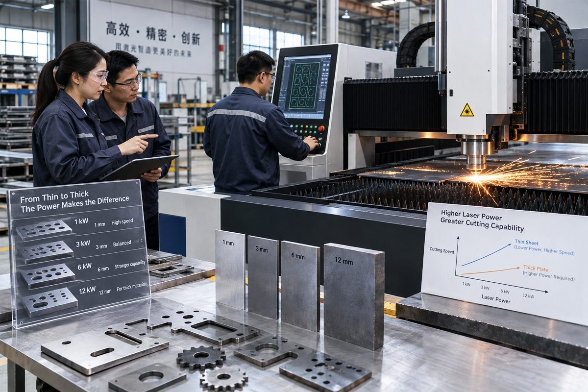
How Does Laser Power Output Affect Laser Cutting Speed and Capability?
Laser power output is one of the most important factors influencing the speed, quality, and overall capability of laser cutting machines. Usually measured in watts or kilowatts, laser power indicates how much optical energy the system can deliver to the workpiece. Higher power generally allows the laser to melt, burn, or vaporize material more quickly, which can increase cutting speed and expand the range of material thicknesses the machine can process. However, power alone does not determine cutting performance.
The effect of laser power varies according to the laser source, material type, material thickness, surface condition, assist gas, focal position, nozzle configuration, and motion-control system. Increasing power may significantly improve productivity when cutting thick carbon steel, stainless steel, or aluminum, but the benefit may be smaller when processing thin sheets. Excessive power or incorrect parameter settings can also create wider kerfs, excessive heat input, rough edges, dross, discoloration, or reduced dimensional accuracy. For this reason, the highest available power is not automatically the most efficient choice for every application.
Laser power also affects more than straight-line cutting speed. It influences piercing time, maximum cutting thickness, edge quality, small-feature accuracy, corner performance, and the machine’s ability to process reflective or thermally conductive materials. The correct power level must therefore balance productivity, quality requirements, equipment cost, energy consumption, and process stability.
Understanding the relationship between power output and cutting performance helps manufacturers select appropriate laser cutting systems and optimize them for specific production goals. This article explains how laser power affects cutting speed and capability, why results differ between materials and thicknesses, and how factors such as beam quality, assist gas, focusing, and machine dynamics determine whether additional power produces a meaningful advantage.
Table of Contents
Understanding Laser Power Output
Laser power output is a fundamental specification of laser cutting systems, but the power rating shown on a machine does not fully describe its cutting performance. To understand what a laser can process, manufacturers must consider how much power reaches the workpiece, how that power is delivered over time, how tightly the beam can be focused, and how efficiently the material absorbs the laser wavelength. These factors collectively determine cutting speed, thickness capability, piercing performance, edge quality, and process stability.
What Laser Power Output Means
Laser power output describes the rate at which laser sources produce optical energy. It is normally measured in watts or kilowatts. One watt equals one joule of energy delivered per second. Therefore, a 6 kW laser can theoretically produce 6,000 joules of optical energy every second when operating at its rated output.
In laser cutting, this energy is focused onto a small area of the workpiece to heat, melt, vaporize, or chemically react with the material. Higher output power can generally supply energy faster, allowing the machine to cut more quickly or penetrate thicker material. It can also shorten piercing times and help maintain stable cutting conditions in materials that conduct heat away from the cutting zone rapidly.
However, power should not be evaluated independently. Material composition, thickness, reflectivity, thermal conductivity, assist gas, cutting speed, focal position, nozzle condition, and beam characteristics all influence how effectively the available power is converted into useful cutting action. A higher-power source may provide greater potential capability, but that potential can only be realized when the entire cutting system is properly configured.
Rated Power Versus Actual Delivered Power
Rated laser power is the nominal maximum output that the laser source is designed to produce under specified operating conditions. For example, a machine advertised as having a 12 kW fiber laser normally contains a source rated to generate approximately 12 kW of optical power. This figure is useful for comparing machine categories, but it is not necessarily the exact amount of power that reaches the material.
As the beam travels from the laser source to the cutting head and through the focusing optics, some energy may be lost. Optical components, protective windows, delivery fibers, mirrors, lenses, and other beam-path elements can absorb or scatter a small portion of the power. Dirty or damaged protective windows can increase these losses considerably and may also distort the beam.
Actual delivered power can also be influenced by source calibration, component condition, thermal management, operating mode, and power-command accuracy. If the source is operated at a percentage of its maximum output, the commanded value should correspond closely to the measured output, but calibration differences may exist. Preventive maintenance and periodic power measurements are therefore important for confirming that the system continues to perform as expected.
Even when full rated power reaches the cutting head, not all of it is absorbed by the workpiece. A portion may be reflected, especially when processing highly reflective materials. The amount absorbed depends on the material, surface condition, laser wavelength, temperature, and angle of incidence. Consequently, the power that produces useful heating in the cut zone can be lower than both the rated source power and the optical power arriving at the surface.
Continuous-Wave and Pulsed Power
Continuous-wave lasers deliver a relatively uninterrupted beam while cutting. Their output is commonly described by average power. Most high-power fiber laser cutting systems operate primarily in continuous-wave mode because a steady energy supply supports fast, stable cutting through sheet and plate materials.
In continuous-wave cutting, increasing average power can raise the amount of energy delivered per second. When the cutting process and motion system can use this additional energy effectively, the machine may achieve higher feed rates, process thicker material, or reduce piercing time. Continuous output is particularly useful for long cutting paths where stable melt formation and consistent material removal are required.
Pulsed lasers deliver energy in a sequence of short pulses rather than as a constant beam. Pulsed operation is characterized by factors such as pulse energy, pulse duration, repetition rate, average power, and peak power. Average power indicates the total energy delivered over time, while peak power indicates the instantaneous power reached during an individual pulse. A pulsed laser can therefore have moderate average power but extremely high peak power.
Pulsed delivery is valuable when precise heat control is required. It can concentrate energy into brief intervals, helping initiate piercing, limit the heat-affected zone, or process delicate and thin materials. Some continuous-wave laser sources can also be modulated rapidly, allowing the output to be switched or adjusted during cutting. The correct delivery mode depends on whether the application prioritizes sustained cutting speed, controlled heat input, piercing performance, or fine-feature quality.
Power Density and Energy Density
Power density describes how much laser power is concentrated within a given area. It is generally expressed in watts per square centimeter or watts per square millimeter. Power density depends on both total output power and focused spot size. If the same power is focused into a smaller spot, the power density increases. If the beam is spread over a larger spot, the power density decreases.
High power density allows the material at the focal point to reach its melting or vaporization temperature rapidly. This is essential for initiating a cut, piercing the workpiece, and maintaining a narrow, stable kerf. However, an extremely small spot is not always ideal. It may provide high intensity but a limited depth of focus, making the process more sensitive to material flatness, focal-position errors, and thickness variations.
Energy density refers to the amount of laser energy delivered to a unit area, commonly expressed in joules per square centimeter. It is affected by power density and exposure time. During cutting, exposure time is closely related to travel speed. Slowing the cutting head increases the energy deposited along a given section of the cutting path, while increasing the speed reduces it.
The correct balance is critical. Insufficient energy density may produce incomplete penetration, intermittent cutting, excessive lower-edge dross, or loss of the cut. Excessive energy density may cause an unnecessarily wide kerf, rounded corners, excessive heat accumulation, edge oxidation, discoloration, or reduced dimensional accuracy. Cutting parameters must therefore coordinate power, speed, focal position, assist-gas pressure, and nozzle selection to deliver the appropriate energy density.
Beam Quality and Usable Power
Beam quality describes how well laser beams can be focused and how closely it approaches an ideal beam profile. It is commonly represented by parameters such as the M² value or beam parameter product. A beam with better quality can generally be focused into a smaller, more concentrated spot and can maintain useful intensity over an appropriate focal range.
This means that two lasers with the same rated output may not produce identical cutting results. A system with favorable beam quality may deliver higher power density at the workpiece, producing faster piercing and more efficient cutting in certain materials. A less effectively focused beam may distribute the same total power across a larger area, reducing its intensity and changing the kerf characteristics.
The ideal beam characteristics also depend on the application. A small, highly concentrated spot can be advantageous for thin materials, narrow kerfs, and fine details. When cutting thicker plate, a different beam profile or a larger effective spot may improve energy distribution through the material thickness and support more efficient molten-material removal. Some advanced laser cutting systems allow beam characteristics to be adjusted for different materials and thicknesses.
Usable power is the portion of the laser’s output that contributes effectively to the cutting process. It depends on source stability, beam delivery, focusing performance, optical cleanliness, material absorption, and parameter optimization. If the nozzle is misaligned, the protective window is contaminated, the focus is incorrect, or the assist-gas flow is unstable, a high-power system may perform below its expected capability. Effective cutting therefore requires the laser source, optics, motion system, cutting head, assist-gas system, and process settings to work together.
Laser power output represents the rate at which laser sources generate optical energy, but the rated power alone does not define cutting capability. Actual performance depends on how much power reaches the workpiece, how efficiently the material absorbs it, how the energy is delivered over time, and how effectively the beam is focused.
Continuous-wave power is well suited to sustained, high-speed cutting, while pulsed or modulated output can provide greater control over piercing, fine features, and heat input. Power density determines how intensely the energy is concentrated, whereas energy density reflects how much energy is applied to an area over time. Beam quality influences focal spot size, intensity, depth of focus, and the amount of power that can be used effectively.
Understanding these relationships makes it easier to compare laser cutting systems and establish suitable cutting parameters. The most capable machine is not simply the one with the highest rated power. It is the system that can deliver stable, well-focused power to the workpiece and coordinate that energy with the material, thickness, assist gas, cutting speed, and required edge quality.
How Laser Cutting Removes Material
Laser cutting removes material by concentrating optical energy into a very small area and creating a narrow separation path known as the kerf. The laser beam does not physically push a tool through the workpiece. Instead, it heats the material until it melts, burns, vaporizes, decomposes, or undergoes a combination of these processes. An assist-gas jet then helps remove the transformed material from the kerf.
The exact removal mechanism depends on the material, laser wavelength, power density, cutting speed, focal position, and assist gas. Understanding these interactions explains why increasing laser power can improve cutting speed and thickness capability, but only when the additional energy can be absorbed, converted into heat, and used to remove material efficiently.
Absorption of Laser Energy
Material removal begins when the workpiece absorbs part of the incident laser energy. The remaining energy may be reflected, transmitted, or scattered. The proportion that is absorbed depends on the material’s optical properties, the laser wavelength, the surface condition, the angle of incidence, and the temperature of the workpiece.
Metals are generally reflective at room temperature, but their absorption often increases as the surface becomes hotter, melts, or oxidizes. This means the beginning of a cut or pierce can be more difficult than maintaining the cut after a molten zone has formed. Materials with high reflectivity and thermal conductivity, such as copper and aluminum, can require greater power density and more carefully controlled parameters because they reflect substantial energy and rapidly conduct heat away from the cutting zone.
The condition of the surface also affects absorption. Oxide layers, coatings, roughness, contamination, and protective films can change how the material interacts with the beam. These surface conditions may improve initial absorption in some cases, but they can also produce inconsistent piercing, smoke, residue, or unstable cutting.
Laser wavelength is another important factor. Fiber lasers emit a wavelength that is absorbed efficiently by many metals, making them highly effective for metal cutting. CO2 lasers operate at a longer wavelength that interacts differently with metals and nonmetallic materials. The laser source must therefore be matched to the material and application.
Once energy is absorbed, it is converted into heat. The rate at which heat is generated depends on the absorbed power and the area over which it is concentrated. Sufficient power density must be maintained to raise the material to the temperature required for the intended removal mechanism.
Heating, Melting, Burning, and Vaporization
The absorbed laser energy first heats the material. As the temperature rises, the material may melt, react with oxygen, vaporize, decompose, or pass through several of these stages. The dominant process depends on the material and cutting method.
In fusion cutting, the laser heats the material above its melting point while a nonreactive assist gas, typically nitrogen, ejects the molten material from the kerf. The gas does not provide a significant chemical heat contribution, so the laser must supply most of the energy required for melting. Fusion cutting can produce clean, oxide-free edges, making it suitable for stainless steel, aluminum, and applications that require high-quality surfaces. However, it often requires more laser power and higher gas pressure than oxygen-assisted cutting.
In reactive cutting, commonly used for carbon steel, oxygen serves as the assist gas. The laser heats the steel to its ignition temperature, after which the iron reacts with oxygen. This exothermic reaction releases additional heat and contributes to the cutting process. As a result, oxygen cutting can process carbon steel with less laser power than would be required to melt the same thickness using an inert gas. The tradeoff is the formation of an oxide layer on the cut edge, and cutting speed may be limited by the reaction rate and the need to maintain process stability.
Vaporization occurs when the material receives enough energy to reach its boiling or sublimation temperature. Some of the material then leaves the cutting zone as vapor. Because vaporization requires considerably more energy than melting alone, it is usually associated with thin materials, high power density, fine features, or specialized cutting conditions. Vapor pressure can help expel material, but excessive vaporization may enlarge the kerf, create plasma, or reduce process efficiency.
Nonmetallic materials may behave differently. Some thermoplastics melt and are blown from the kerf, while others vaporize or chemically decompose. Wood, paper, textiles, and similar organic materials undergo thermal decomposition and combustion. The resulting gases, smoke, particles, and molten residue must be extracted effectively. Material composition must always be evaluated because some substances can release corrosive or toxic fumes when heated.
In practical cutting, these mechanisms often overlap. A metal may melt while a small portion vaporizes, and chemical reactions may occur at the same time. The goal is not simply to produce the highest temperature, but to create a controlled removal process that separates the material with the required speed and edge quality.
Removal of Molten Material
Heating or melting the material is only part of the cutting process. The transformed material must be removed from the kerf before it cools and solidifies. If it is not expelled effectively, the cut may remain incomplete or develop heavy dross along the lower edge.
The assist gas is delivered through a nozzle positioned above the workpiece, usually in alignment with the laser beam. The resulting high-speed gas jet enters the kerf and pushes molten material downward and away from the cutting zone. Gas type, pressure, nozzle diameter, nozzle-to-workpiece distance, and beam-to-nozzle centering all affect removal efficiency.
Nitrogen is commonly supplied at high pressure because its primary role is to eject molten material and prevent oxidation. Oxygen may operate at lower pressure because it also supports the exothermic reaction. Compressed air can be used for certain applications as a lower-cost alternative, although its oxygen and moisture content can affect edge appearance and process consistency.
Kerf geometry also influences material removal. A kerf that is too narrow may restrict gas flow and make it difficult to eject molten material through the full thickness. An unnecessarily wide kerf removes more material, increases heat input, and may reduce dimensional accuracy. The focus position and beam profile must create a kerf that supports efficient gas flow from the top surface to the bottom of the cut.
Molten-material behavior is also affected by viscosity, surface tension, temperature, gravity, and the movement of the cutting front. If the cutting speed is too high, the laser may not generate enough molten material through the full thickness, causing incomplete penetration. If the speed is too low, excessive melting can increase kerf width, roughness, and dross. Stable cutting requires the melt to form and leave the kerf continuously.
The Cutting Energy Balance
Laser cutting depends on an energy balance between the energy entering the cutting zone and the energy required or lost during the process. Energy enters primarily through the absorbed laser beam. In oxygen-assisted cutting, chemical reactions provide an additional source of heat. This input energy must be sufficient to heat the material, produce melting or vaporization, maintain the cutting front, and compensate for energy losses.
Some heat is conducted from the cutting zone into the surrounding workpiece. Materials with high thermal conductivity remove heat rapidly, which can make it more difficult to establish and sustain the cut. Energy is also lost through radiation, convection, reflected laser light, escaping hot gases, and expelled molten material. The machine must provide enough usable energy to overcome these losses without creating excessive heating outside the intended kerf.
Cutting speed directly affects this balance. At a slower speed, the beam interacts with each section of material for longer, increasing the energy delivered per unit length. At a higher speed, the interaction time decreases. Increasing laser power can allow the machine to maintain sufficient energy per unit length at a faster feed rate, but the gain continues only while the material-removal process and machine dynamics can keep pace.
If energy input is too low, the beam may fail to penetrate the material completely, or the molten material may not remain fluid enough to be expelled. If the input is too high, the process can produce an oversized kerf, excessive heat-affected zones, rounded corners, heavy oxidation, burning, or loss of fine-detail accuracy.
The optimum energy balance is therefore different for every combination of material, thickness, assist gas, and quality requirement. Laser power must be coordinated with cutting speed, focal position, beam characteristics, gas delivery, and motion control to produce a stable cutting front and consistent material removal.
Laser cutting removes material through a sequence of energy absorption, heating, material transformation, and ejection. The workpiece absorbs laser energy and converts it into heat, causing the material to melt, burn, vaporize, decompose, or react chemically. An assist-gas jet then removes molten or reacted material from the kerf and keeps the cutting path open.
Successful cutting requires more than enough power to heat the surface. The laser must maintain the required temperature through the material thickness, while the assist gas must remove the transformed material before it resolidifies. At the same time, the process must compensate for heat conduction, reflection, radiation, and other energy losses.
Laser power can increase cutting speed and thickness capability by supplying energy more rapidly. However, useful performance depends on whether that energy is absorbed effectively and balanced with material properties, cutting speed, beam focus, assist-gas flow, and kerf geometry. The most efficient process delivers enough energy to sustain clean material removal without introducing unnecessary heat or reducing cut quality.
How Laser Power Affects Cutting Speed
Laser power directly influences how quickly laser cutting systems can deliver enough energy to heat, melt, burn, or vaporize material. In general, greater usable power enables faster cutting because the machine can supply the required energy in less time. However, the relationship between power and speed is not a simple one-to-one ratio. Material properties, thickness, beam quality, focal position, assist gas, machine acceleration, and required edge quality determine how much additional speed can actually be achieved.
It is also important to distinguish cutting speed from overall production speed. Cutting speed describes how rapidly the laser moves while actively cutting, whereas total productivity includes piercing, positioning, acceleration, deceleration, part unloading, and other noncutting operations. Higher power may significantly increase the programmed cutting speed without producing an equivalent increase in completed parts per hour.
The Basic Power–Speed Relationship
As the laser moves along the cutting path, it must deliver enough absorbed energy per unit length to create and maintain the kerf. At a basic level, the energy supplied per unit length is related to laser power divided by cutting speed. Increasing power makes more energy available each second, while increasing speed reduces the time the beam interacts with each section of material.
If the original process has sufficient stability and the other parameters remain suitable, higher laser power allows the cutting head to travel faster while maintaining the energy required for full penetration. This can improve productivity, reduce cutting time, and help prevent excessive heat accumulation around the kerf.
The available power must still be absorbed and converted into useful cutting energy. Some energy is reflected, conducted into the surrounding workpiece, or lost through radiation and escaping gases. Furthermore, the molten material must be expelled from the kerf quickly enough to match the higher cutting speed. The useful relationship is therefore between absorbed power and stable material removal—not simply between rated source power and commanded feed rate.
Why Cutting Speed Does Not Increase Linearly with Power
Doubling laser power does not usually double cutting speed. A portion of the additional power is consumed by heat losses, changes in kerf geometry, inefficient absorption, plasma formation, and other process effects. As speed increases, the cutting front changes shape, and the assist gas has less time to remove molten material. Eventually, melt ejection rather than available laser power becomes the limiting factor.
The response also varies by material and thickness. Thin material may already be cut near the acceleration limit of the machine, so additional power produces only a modest speed increase. Thick material may absorb more power effectively, but the beam must maintain sufficient energy density through the entire thickness. Increasing power without adjusting focus, nozzle selection, gas pressure, and beam characteristics may not improve the lower portion of the cut.
Cut quality creates another limitation. A parameter that achieves separation at a very high speed may produce excessive striations, incomplete corners, lower-edge dross, or an inconsistent kerf. Production speed must therefore be based on an acceptable quality standard rather than the fastest speed at which the material can be separated.
The influence of assist gas further prevents a linear relationship. In oxygen cutting, part of the cutting energy comes from the exothermic reaction between oxygen and hot steel. More laser power does not necessarily accelerate this chemical reaction proportionally. In nitrogen cutting, the laser supplies most of the melting energy, but gas flow and pressure must still be capable of ejecting the increased volume of molten material.
Minimum Power Required to Sustain a Cut
Every material and thickness combination has a minimum level of usable power density and energy input required to establish and sustain a cut. The laser must heat the material through its thickness, maintain a continuous cutting front, and keep the molten zone fluid enough for the assist gas to remove it.
If power is below the required threshold, the beam may only mark or partially melt the surface. The cut may begin successfully after piercing but fail during motion, particularly around areas affected by surface variation, material composition, thermal conduction, or changes in direction. Typical symptoms include incomplete penetration, intermittent cutting, heavy dross, sparks returning upward, and sections that remain attached.
Reducing cutting speed can sometimes compensate for limited power because it increases the interaction time and energy delivered per unit length. However, slowing the machine has practical limits. Excessive dwell time can widen the kerf, enlarge the heat-affected zone, cause severe oxidation, and allow molten material to resolidify along the lower edge. If the available power is too low for the material thickness, reducing speed alone will not produce an efficient or reliable process.
The minimum sustainable power is not a fixed universal value. It depends on the laser wavelength, beam quality, focal position, material grade, surface condition, assist gas, nozzle configuration, and required edge quality. Stable production normally requires an operating margin above the absolute cutting threshold to accommodate normal variations in material and machine condition.
Maximum Effective Cutting Speed
Maximum effective cutting speed is the highest speed at which the system can consistently produce complete cuts that meet the required quality standard. It is lower than the speed at which the laser merely begins to lose penetration, because reliable manufacturing requires a margin for variation.
As speed approaches the process limit, the cutting front can become unstable. The beam may no longer deliver enough energy to the lower portion of the material, and the assist gas may fail to remove the molten material completely. This can result in trailing striations, lower-edge dross, incomplete separation, rough surfaces, or sudden loss of the cut.
Mechanical performance can also establish the maximum effective speed. The cutting head must accelerate, decelerate, and change direction while following the programmed path accurately. On short contours, the machine may never reach the nominal feed rate before it must slow down again. Motion-control capability, axis acceleration, frame rigidity, servo response, and CNC look-ahead functions can therefore become more important than laser power.
Maximum effective speed must be determined using the actual production material, thickness, geometry, gas supply, and quality requirements. Parameter testing should evaluate not only whether the part separates, but also edge roughness, dross, kerf width, dimensional accuracy, heat effects, and process repeatability.
Speed Gains in Thin Materials
Higher laser power can produce very high cutting speeds in thin sheet because relatively little material must be melted and removed. The beam passes through the thickness quickly, and the machine can move rapidly while still delivering sufficient energy per unit length.
However, speed gains in thin material often reach a point of diminishing returns. Once the laser can melt the material faster than the motion system can follow the programmed geometry, additional power provides limited benefit. Machine acceleration, cornering performance, and path complexity become the primary constraints.
Excessive power may also reduce quality if it is not matched with suitable speed and focus settings. It can create a wider kerf, excessive heat input, rounded features, unstable corners, or damage to small contours. Modern cutting systems may use reduced power, pulsed output, or automatic power modulation during corners and tight features to maintain accuracy.
For thin-sheet production, total cycle time is strongly affected by piercing, rapid movement, contour length, and the number of individual parts. Higher power is most valuable when the cutting program contains long paths where the machine can reach and maintain the increased feed rate. On densely nested parts with many short cuts, improved acceleration and faster piercing may have a greater effect on productivity than additional cutting power alone.
Speed Gains in Thick Materials
When cutting thick material, a larger volume must be heated and removed from the kerf. More power can improve penetration, shorten piercing time, increase cutting speed, and expand the maximum processable thickness. The benefit is often substantial when moving from a power level that is close to the minimum cutting threshold to one that provides a stable production margin.
Nevertheless, thick-material cutting presents limitations that power alone cannot solve. The beam must maintain sufficient intensity through the full thickness, and the assist gas must travel deep into the kerf to expel molten material. Kerf width, beam profile, focal depth, nozzle design, gas purity, gas pressure, and material flatness become increasingly important.
Inert-gas cutting of thick stainless steel or aluminum generally requires significant laser power because the laser must supply most of the melting energy. Higher power can increase speed, but gas-flow limitations and molten-material behavior eventually restrict further gains. In oxygen cutting of carbon steel, the chemical reaction supplies part of the energy, so a large increase in laser power may not create a proportional speed increase. Excessive power or speed can disturb the controlled oxidation process and reduce edge quality.
As thickness increases, the acceptable process window can become narrower. A small change in focus, nozzle centering, lens condition, or material quality may cause cut failure. For this reason, stable capability and acceptable edge quality are often more important than the highest possible feed rate.
Cutting Straight Lines Versus Complex Profiles
Straight lines allow the cutting head to accelerate to a high speed and maintain it over a longer distance. These paths can take better advantage of increased laser power because the machine operates close to the programmed feed rate for more of the cut. Long, gently curved contours can provide similar benefits.
Complex profiles contain corners, small holes, narrow slots, short line segments, and frequent direction changes. The machine must repeatedly decelerate and accelerate to follow these features accurately. Consequently, the average cutting speed may be much lower than the maximum speed specified for the material.
If the laser continues delivering full power while the cutting head slows at a corner, excess heat can accumulate. This may cause corner burning, enlarged kerfs, loss of sharpness, excessive oxidation, or deformation. CNC systems compensate by dynamically adjusting laser power, frequency, duty cycle, gas conditions, or feed rate according to the instantaneous motion of the cutting head.
Small holes are especially sensitive because heat is concentrated within a limited area. The optimum settings for a long straight cut may be unsuitable for a hole with a diameter close to the material thickness. Lower power, reduced speed, pulsed operation, specialized lead-ins, or alternative piercing strategies may be required.
As a result, higher power provides the greatest speed advantage on geometries that allow sustained motion. For intricate parts, productivity depends on the coordination of laser output and motion control rather than maximum power alone.
Higher laser power generally increases cutting speed by supplying the energy required to melt or react with material in less time. It can help sustain a cut at faster feed rates, reduce piercing time, and improve the ability to process thicker material. However, cutting speed does not rise in direct proportion to power because absorption, heat loss, assist-gas performance, melt ejection, beam characteristics, and machine dynamics impose additional limits.
Thin materials may reach the mechanical speed and acceleration limits of the machine before they use all the available laser power. Thick materials can benefit substantially from higher power, but stable cutting also depends on focus, beam profile, kerf geometry, gas flow, and full-thickness material removal. Straight paths can make better use of high power and high feed rates, while complex contours require frequent speed and power adjustments to preserve accuracy.
The most effective process uses enough power to maintain a stable cut at the desired speed while satisfying edge-quality and dimensional requirements. Evaluating power together with material thickness, geometry, gas system, beam delivery, and motion performance provides a more realistic measure of productivity than rated wattage alone.
How Laser Power Affects Material Thickness Capability
Laser power is a major factor in determining the thickness range laser cutting machines can process. Thicker material requires more energy because the beam must establish and maintain a cutting front through a greater depth while the assist gas removes a larger volume of molten or reacted material. Increasing power can expand the machine’s thickness capability, improve piercing performance, and provide a wider operating window. However, maximum thickness is not determined by wattage alone. Beam quality, focal depth, material properties, assist gas, nozzle configuration, cutting speed, and acceptable edge quality all influence the practical result.
Power and Penetration Depth
In laser cutting, penetration depth does not mean that the laser beam passes deeply into solid material before being absorbed. For most metals, optical energy is absorbed near the surface or at the exposed cutting front. The cut progresses through the thickness as absorbed energy heats the material and creates a molten, vaporized, or chemically reacting zone.
Higher laser power delivers more energy per unit time, making it easier to maintain the required temperature from the top surface to the bottom of the workpiece. This is especially important during piercing, when the laser must create an initial hole through the full thickness before contour cutting can begin. Greater usable power can shorten piercing time and improve the reliability of penetration, although piercing parameters must be controlled to prevent excessive spatter, crater formation, or damage to the cutting head.
Once the cut begins, the beam interacts with the inclined cutting front inside the kerf. The focus position, beam profile, and depth of focus determine how energy is distributed through the material. A tightly focused beam can produce high power density near the surface, but it may not maintain the ideal intensity throughout a thick plate. Thick-material cutting may therefore require a different focal position or beam characteristic than thin-sheet cutting.
Increasing power supports greater thickness only when the energy reaches the lower part of the cutting front, and the molten material can be removed effectively. If the kerf is too narrow, the focus is incorrect, or the assist-gas jet cannot reach the lower section, additional power may increase heating without producing complete penetration.
Maximum Cuttable Thickness
Maximum cuttable thickness is the greatest material thickness that a machine can separate under suitable conditions. It is usually established using a specific material grade, surface condition, assist gas, nozzle, focal position, and cutting parameter set. Changing any of these factors can alter the result.
As thickness increases, the laser must supply enough energy to maintain a continuous cutting front, while the assist gas must remove molten material through a deeper and longer kerf. Heat conduction into the surrounding workpiece also increases the energy demand. Eventually, the process reaches a limit where the available power density, focal range, or gas flow can no longer maintain stable separation.
The advertised maximum thickness should therefore be interpreted carefully. It may represent a demonstrated cut under optimized conditions rather than a thickness suitable for continuous production. The resulting edge may have pronounced striations, substantial taper, heavy dross, a wide kerf, or a long processing time. Some maximum-thickness cuts may also require specialized piercing strategies, high gas consumption, or frequent monitoring.
Laser source power is only one component of the maximum-thickness rating. Beam quality, cutting-head design, optical condition, nozzle alignment, gas purity, gas pressure, machine stability, and parameter control all affect whether the rated capability can be achieved. Material quality is equally important because variations in composition, thickness, surface scale, flatness, and internal stress can narrow the process window.
Maximum Thickness Versus Production Thickness
Maximum thickness and practical production thickness are not the same. Maximum thickness describes the boundary at which separation is technically possible, whereas production thickness describes the range that can be cut repeatedly at an acceptable speed, quality, and operating cost.
A machine operating at its absolute thickness limit may require very slow cutting speeds and long piercing cycles. Small variations in the material, focus position, nozzle condition, or gas supply may cause incomplete cuts. Edge roughness and dross may also increase, leading to additional grinding or finishing work. Although the machine can cut the material, the process may not be economical or sufficiently reliable for regular manufacturing.
Production thickness should provide a reasonable process margin. The machine must accommodate normal variations in plate condition and maintain consistent results over long cutting periods. It should also produce edges that satisfy the application’s requirements without excessive secondary processing.
The appropriate production limit depends on the required result. A fabrication shop producing general structural components may accept slower speeds and rougher edges than a manufacturer producing precision parts for direct assembly. Similarly, occasional thick-plate cutting may justify operating near the machine’s maximum capacity, while high-volume production generally requires a wider stability margin.
When comparing laser cutting systems, buyers should evaluate demonstrated production results rather than relying only on maximum-thickness claims. Relevant considerations include piercing time, cutting speed, edge roughness, taper, dross, gas consumption, repeatability, and the amount of postprocessing required.
Why Thickness Capacity Differs by Material
Different materials require different amounts of usable energy and respond differently to the laser beam. Reflectivity, absorptivity, thermal conductivity, melting temperature, chemical composition, viscosity, and surface condition all affect thickness capability.
Carbon steel is often cut with oxygen. After the laser heats the material to its ignition temperature, the reaction between iron and oxygen releases additional heat. This exothermic contribution allows relatively thick carbon steel to be processed with less laser power than would be required if the material were melted entirely by laser energy. However, oxygen cutting produces an oxidized edge and is sensitive to reaction stability.
Stainless steel is commonly cut with nitrogen when an oxide-free edge is required. Because nitrogen does not provide meaningful reaction heat, the laser must supply nearly all the energy needed to melt the material. High-pressure nitrogen must then eject the molten metal from the kerf. The required laser power and gas consumption rise significantly as thickness increases.
Aluminum combines high thermal conductivity with relatively high reflectivity. Heat spreads rapidly away from the cutting zone, and the material may require greater power density to initiate and maintain the cut. Molten aluminum must also be removed efficiently to prevent lower-edge dross. Modern fiber lasers can cut aluminum effectively, but the practical thickness limit depends heavily on power, beam delivery, focus, and gas performance.
Copper and brass are highly reflective and thermally conductive, making them more challenging than many steels. Suitable laser wavelengths, stable back-reflection protection, high power density, and carefully optimized parameters are required. Their maximum thickness at a given power level is generally lower than that of carbon steel.
The physical behavior of the molten material also matters. Viscosity and surface tension influence how readily the assist gas can push the melt through the kerf. Material composition and alloying elements can change edge roughness, dross formation, and process stability. Two materials of the same thickness may therefore require substantially different power levels, cutting speeds, gas conditions, and focal settings.
Power Reserve and Process Stability
Power reserve is the difference between the power required to make a marginal cut and the power available for maintaining a reliable production process. A machine operating continuously at the minimum threshold has little ability to compensate for changes in material condition, optical transmission, nozzle wear, gas pressure, or environmental conditions.
Adequate power reserve creates a wider processing window. It allows the machine to sustain full penetration when the material surface varies, the plate is slightly thicker than its nominal specification, or the cutting path passes through an area with different thermal behavior. It can also support faster piercing and reduce the risk of losing the cut during long production cycles.
Power reserve does not mean that the machine should always operate at maximum output. Excessive power can increase kerf width, heat input, oxidation, and the risk of corner damage. In many applications, the control system adjusts power according to material thickness, cutting speed, geometry, and instantaneous axis movement. The value of additional power lies in having sufficient capacity when it is needed, rather than applying full power under every condition.
Process stability also depends on maintaining the complete optical and gas-delivery system. A contaminated protective window, misaligned nozzle, incorrect focal position, unstable gas supply, or degraded optical component can reduce usable power at the workpiece. Regular inspection and maintenance help preserve the reserve originally designed into the process.
For manufacturers that regularly cut near the upper end of a machine’s thickness range, selecting a higher-power system may improve reliability and productivity. However, the decision should also consider acquisition cost, electrical consumption, gas demand, cutting-head capability, and whether the expected workload can use the additional capacity efficiently.
Higher laser power generally increases material thickness capability by delivering more energy to the cutting front and helping the machine maintain penetration through a deeper kerf. It can shorten piercing time, improve cutting stability, and expand the range of materials that can be processed. However, power alone cannot guarantee a successful thick-material cut.
Maximum cuttable thickness represents the technical boundary of the process, while production thickness reflects the range that can be cut consistently at an acceptable speed, quality, and cost. The production range is usually lower because reliable manufacturing requires tolerance for normal variations in material and machine condition.
Thickness capability also differs significantly by material. Carbon steel can benefit from the heat generated during oxygen cutting, while stainless steel, aluminum, copper, and brass depend more heavily on laser energy, absorption behavior, and efficient melt ejection. Beam quality, focal position, assist-gas performance, kerf geometry, and optical condition all affect the usable result.
Suitable laser cutting systems should therefore provide enough power for the required thickness while maintaining an appropriate process reserve. The best choice is not simply the machine with the largest maximum-thickness claim, but the one that can produce the required parts repeatedly with stable quality, reasonable speed, and manageable operating costs.
How Laser Power Influences Cutting Quality
Laser power affects not only how quickly and how deeply a machine can cut, but also the appearance, accuracy, and usability of the finished edge. The correct power level must provide enough energy to maintain full penetration and stable material removal without creating unnecessary heat. Too little power can cause incomplete cuts, rough edges, and persistent dross, while excessive power can enlarge the kerf, overheat small features, and reduce dimensional accuracy.
Cutting quality is determined by the interaction of laser power with cutting speed, focal position, beam quality, assist-gas type and pressure, nozzle condition, and material properties. Power should therefore be optimized as part of the complete process rather than adjusted independently.
Kerf Width
Kerf width is the width of the material removed by the laser. It affects dimensional accuracy, part spacing, nesting efficiency, and the amount of compensation required in the cutting program. The kerf is influenced by laser power, focused spot size, focal position, cutting speed, material thickness, and assist-gas flow.
Increasing power can widen the kerf if the cutting speed and other parameters remain unchanged. More energy melts a larger volume of material and can enlarge the heat-affected area surrounding the beam. However, higher power may also allow the machine to cut faster, reducing interaction time and limiting unnecessary kerf growth. The final result depends on the balance between power and speed.
If power is too low, the kerf may become narrow or irregular near the bottom because the beam cannot maintain sufficient energy through the full thickness. This can cause incomplete separation, severe taper, or lower-edge dross. If power is excessive, the top of the kerf may become unnecessarily wide, particularly when the focal position is too high or the cutting speed is too slow.
A stable kerf requires consistent beam focusing and effective assist-gas flow. Nozzle misalignment, contaminated optics, improper focus, or variable plate height can cause the kerf width to change along the cutting path. Kerf compensation should therefore be established only after a stable cutting process has been achieved.
Edge Roughness and Striation Patterns
Laser-cut edges normally display fine vertical or slightly curved lines known as striations. These patterns form as the cutting front moves through the material and molten material flows downward through the kerf. Their spacing, depth, angle, and consistency provide useful information about cutting stability.
When laser power is correctly matched to the cutting speed, the cutting front remains stable, and the molten material leaves the kerf continuously. This generally produces fine, uniform striations and a smoother edge. If power is insufficient, the lower portion of the material may not remain fully molten. The striations can become coarse, irregular, strongly curved, or accompanied by attached material.
Excessive power can also reduce edge quality. Too much heat may enlarge the molten zone, disturb the cutting front, or promote excessive oxidation. This can create an irregular surface even though the material separates. Increasing power without increasing speed may therefore make the edge rougher rather than smoother.
Material thickness affects the result. Thin sheet can often be cut with a relatively smooth edge because the beam penetrates the material quickly. In thick plate, the molten material must travel farther before leaving the kerf, increasing the opportunity for flow instability. Beam profile, focal position, gas pressure, and nozzle alignment become increasingly important as thickness rises.
The smoothest edge is not always produced at the highest possible cutting speed. A machine may achieve complete separation at a fast feed rate while leaving unacceptable striations. Cutting parameters should be selected according to the required edge standard, not solely according to maximum productivity.
Dross and Slag Formation
Dross is resolidified material that remains attached to the lower edge of a laser-cut part. In oxygen cutting, oxidized residue may also be described as slag. Dross forms when molten or reacted material is not expelled completely before it cools.
Insufficient power is a common cause of dross because the lower part of the cutting front may not remain hot enough for the material to flow freely. The melt becomes more viscous and attaches to the bottom edge. Cutting too quickly can produce a similar result by reducing the energy delivered per unit length.
Excessive power or an unnecessarily slow cutting speed can create a different type of dross. Too much material may be melted, and the assist gas may be unable to remove the increased volume efficiently. The enlarged molten zone can produce rounded lower edges and heavy, strongly attached deposits.
Laser power must be coordinated with gas pressure and kerf geometry. Even when enough energy is available, dross may form if the gas pressure is too low, the nozzle is damaged, the beam is not centered in the nozzle, or the nozzle-to-workpiece distance is incorrect. An overly narrow kerf may also restrict gas flow and prevent the melt from escaping.
Different materials produce different types of dross because their molten viscosity, surface tension, thermal conductivity, and oxidation behavior vary. Eliminating dross may require adjusting power, speed, focal position, gas type, gas pressure, and nozzle size together.
Heat-Affected Zone
The heat-affected zone is the region next to the cut edge where the material’s microstructure or properties have been altered by heat without being removed. Its importance depends on the material and the final application. An excessive heat-affected zone can affect hardness, strength, corrosion behavior, coating adhesion, or subsequent forming and welding operations.
Higher power does not automatically create a larger heat-affected zone. If additional power allows the machine to cut significantly faster, the beam may spend less time over each section of material, limiting lateral heat conduction. In this situation, a higher-power process can achieve greater productivity while maintaining or even reducing thermal exposure.
However, applying high power at an unnecessarily slow speed increases energy input per unit length. More heat can spread into the surrounding material, enlarging the heat-affected zone and increasing the risk of distortion. This is particularly important for thin sheets, narrow webs, small parts, and heat-sensitive materials.
Assist gas also influences the thermal result. Oxygen cutting adds heat through an exothermic reaction and produces an oxidized edge. Nitrogen removes molten material without contributing significant chemical heat, although high laser power may still be required. Effective gas flow can help remove heat and molten material from the kerf.
Controlling the heat-affected zone requires an appropriate balance of power and speed. The objective is to deliver enough energy to complete the cut rapidly without allowing excessive heat to accumulate in the surrounding workpiece.
Edge Squareness and Taper
An ideal laser-cut edge is perpendicular to the upper and lower surfaces of the material. In practice, the kerf may be wider at the top or bottom, creating taper. Edge squareness is particularly important when parts must fit together precisely, undergo welding, or be used without secondary machining.
Laser power influences taper by affecting the amount and distribution of energy through the material thickness. If power is insufficient at the lower cutting front, the bottom of the kerf may remain narrower than the top. This produces a tapered edge and may also cause lower-edge dross.
Increasing power can improve edge squareness by maintaining a more consistent molten zone through the thickness. However, power must be delivered with an appropriate beam profile and focal position. Excessive energy concentrated near the top surface can widen the upper kerf without improving the lower section, increasing rather than reducing taper.
The focal position determines where maximum power density occurs relative to the workpiece. Thin and thick materials often require different focus settings. Thick plate may need the energy distributed deeper into the kerf to support full-thickness melting and material removal.
Nozzle alignment and assist-gas flow are also essential. An off-center gas jet can remove molten material unevenly and produce different edge angles on opposite sides of the kerf. Accurate height control helps keep the beam and gas conditions consistent across the workpiece.
Surface Oxidation and Discoloration
Power affects the thermal and chemical conditions of the cut edge. When oxygen is used as the assist gas, oxidation is part of the cutting mechanism. The resulting edge normally develops an oxide layer that may need to be removed before painting, coating, or welding.
Higher power can change the intensity and extent of oxidation by raising the edge temperature. However, oxygen pressure, purity, cutting speed, and material composition also influence oxide formation. Excessive power or a slow cutting speed may create a thicker, less uniform oxide layer and increase heat tint around the cut.
Nitrogen is commonly used when a bright, oxide-free edge is required. It prevents significant oxidation by shielding the hot metal from atmospheric oxygen and ejecting molten material from the kerf. Because nitrogen does not provide reaction heat, sufficient laser power is required to melt the material at the desired speed.
Compressed air contains oxygen and can produce some edge oxidation or discoloration. The result depends on the material, thickness, air quality, pressure, and power setting. Oil, moisture, or other contaminants in the air supply can also affect edge appearance.
Discoloration may indicate excessive heat input, inadequate gas shielding, gas contamination, or insufficient flow. Increasing power alone will not correct these conditions and may intensify them. Power, speed, and gas delivery must be adjusted together to achieve the required surface condition.
Fine Features and Dimensional Accuracy
High laser power can improve productivity, but it must be controlled carefully when cutting small holes, narrow slots, sharp corners, and closely spaced contours. These features contain short cutting paths and frequent changes in direction, which reduce the time available for the machine to reach its programmed speed.
When the cutting head slows for a corner or small radius, the laser delivers more energy per unit length unless power is reduced proportionally. Excess energy can enlarge the kerf, round sharp corners, distort small holes, or melt narrow sections between adjacent cuts. Heat accumulation can also cause thin parts to move or warp.
Insufficient power creates different accuracy problems. The laser may fail to penetrate fully, especially during small-hole cutting or after rapid direction changes. An unstable cutting front can produce irregular kerf width, rough contours, or features that remain partially attached.
Modern laser cutting systems use dynamic power control to match the output to the actual cutting speed. Power may be reduced during acceleration, deceleration, cornering, and small-feature cutting, then increased when the machine returns to a long straight path. Pulsed or modulated output may also be used to limit heat accumulation.
Dimensional accuracy depends on more than power. Beam size, kerf compensation, machine calibration, focus stability, material flatness, thermal expansion, and motion-control accuracy all contribute to the finished dimensions. The optimum power is the level that maintains stable penetration while preserving the geometry of the feature.
Laser power influences nearly every aspect of cutting quality, including kerf width, edge roughness, dross, heat effects, taper, oxidation, and dimensional accuracy. Too little power can produce incomplete penetration, irregular striations, narrow lower kerfs, and persistent dross. Too much power can enlarge the molten zone, widen the kerf, overheat small features, and increase oxidation or distortion.
The relationship is not determined by power alone. Cutting speed controls how long the beam interacts with each area, while focal position and beam quality determine how energy is distributed through the thickness. Assist-gas type, pressure, nozzle condition, and alignment control how effectively molten material is removed and whether the edge oxidizes.
High power can produce excellent quality when it is paired with faster movement and suitable process settings. It becomes detrimental when the machine applies more energy than the material and geometry require. The best cutting quality comes from balancing power with speed, focus, gas delivery, material properties, thickness, and feature size. This coordinated approach maintains stable penetration while minimizing thermal damage and preserving the required edge condition and dimensional accuracy.
Laser Power and Piercing Performance
Before contour cutting can begin inside a sheet or plate, the laser must create an initial hole through the material. This process is known as piercing. Although piercing and cutting use the same laser source, they require different power delivery, timing, focal positions, and assist-gas conditions. During cutting, the beam moves along an open kerf through which molten material can escape. During piercing, the beam concentrates energy in one area while gradually forming a narrow channel through the full thickness.
Laser power strongly affects piercing speed and thickness capability, but simply applying maximum output is not always the best approach. A successful piercing process must penetrate the material quickly while controlling spatter, heat accumulation, hole size, and the risk of damage to the cutting head.
Why Piercing Requires Different Conditions
Piercing begins on a solid surface without an existing kerf. The laser must first heat the surface, create a molten zone, and deepen the cavity until it passes through the bottom of the material. Before full penetration occurs, molten material, vapor, sparks, and process gases must escape primarily through the top of the developing hole. This upward flow makes piercing more unstable than normal contour cutting.
Because the beam remains over a relatively small area, heat accumulates rapidly. Parameters that work well during continuous cutting may create an oversized crater, excessive spatter, or severe oxidation when used for piercing. The machine may therefore apply a dedicated combination of laser power, pulse frequency, duty cycle, focal position, assist-gas pressure, and piercing time.
Different piercing strategies may be used according to the material and thickness. Thin sheets can often be pierced rapidly with a short pulse or brief application of continuous power. Thick plates may require staged or progressive piercing in which power, focus, and gas conditions change during different phases. This controlled approach allows the hole to deepen while limiting unstable ejection and excessive surface damage.
The position of the pierce also matters. Piercing is normally performed within scrap material or on a lead-in path so that the crater does not affect the final part edge. For small contours, the available lead-in space may be limited, making accurate control of pierce diameter and thermal damage especially important.
How Higher Power Reduces Piercing Time
Higher laser power can reduce piercing time by supplying the energy needed to heat, melt, and remove material more rapidly. It helps the process reach the melting or ignition temperature sooner and can increase the rate at which the piercing cavity progresses through the thickness.
The advantage becomes particularly important in production programs containing many separate contours. Each contour may require a new pierce, so even a small reduction in piercing time can produce a significant improvement in the total cycle time. Faster piercing also reduces the time the cutting head remains stationary over one location.
Higher power can expand the range of materials and thicknesses that can be pierced reliably. It provides a greater energy reserve for overcoming reflection, heat conduction, surface scale, and variations in plate condition. However, the additional power must be delivered in a controlled way. The most effective strategy may use a high peak power with a managed pulse duration or duty cycle rather than uninterrupted maximum output.
Piercing speed also depends on beam quality and focus. A well-focused beam creates the power density needed to initiate melting rapidly, while an appropriate focal position directs energy into the developing cavity. Assist gas helps remove molten material and clear vapor from the hole. Higher power provides the energy, but optical and gas conditions determine how efficiently that energy produces penetration.
Risks of Excessive Piercing Power
Excessive piercing power can melt or vaporize material faster than it can escape. Pressure may build inside the developing cavity, ejecting molten droplets and sparks upward toward the nozzle and protective window. This spatter can contaminate or damage optical components, reduce beam transmission, and interrupt production.
Too much power can also create an oversized pierce crater. The top surface may become excessively melted, producing a large entry hole, irregular edges, or a raised rim of resolidified material. If the pierce is positioned too close to the finished contour, this damage may extend into the usable part.
Rapid heat accumulation can cause severe oxidation, discoloration, distortion, or delamination of surface coatings. On thin material, excessive power may create a violent blowout rather than a controlled hole. On thick material, it may form a large molten cavity near the top without successfully extending the pierce through the bottom.
Another risk is unstable plasma or vapor formation. A dense cloud above or inside the hole can interfere with energy delivery and make the process inconsistent. Excessive gas pressure can compound the problem by increasing upward ejection before a clear path exists through the material.
For these reasons, piercing parameters often use power modulation. The control system may begin with a selected pulse pattern, adjust duty cycle as the cavity deepens, and switch to cutting parameters only after full penetration is confirmed. The objective is to achieve the shortest reliable piercing time rather than the most aggressive possible energy input.
Piercing Thick Materials
Thick materials require more time and energy to pierce because the laser must create a deeper channel and remove a greater volume of material. The longer cavity also restricts the escape of molten material and process gases. As penetration advances, maintaining effective energy delivery to the bottom of the hole becomes increasingly difficult.
A staged piercing process is often used. The machine may begin with parameters designed to establish the initial cavity, followed by one or more stages that progressively deepen and stabilize the hole. Laser power, pulse frequency, duty cycle, focal position, nozzle height, and gas pressure may change during this sequence.
The most suitable method depends on the material and assist gas. Oxygen can support piercing of carbon steel by generating additional heat through an exothermic reaction, but the reaction must be controlled to prevent excessive burning and an enlarged crater. Nitrogen piercing relies more heavily on laser energy and high-pressure gas to melt and expel material, which can increase the required power and gas consumption.
Power reserve is especially important when piercing thick plate. A machine operating close to its maximum capability may be sensitive to surface scale, rust, coatings, thickness variations, or minor optical contamination. Additional available power can improve reliability, but only if the cutting head, optics, and gas-delivery system are designed to handle it.
Modern systems may monitor the process to determine when breakthrough occurs. Ending the piercing cycle immediately after penetration prevents unnecessary heat input and saves time. If the machine begins contour cutting before breakthrough, it may lose the cut and damage the part. If it waits too long, it wastes energy and enlarges the pierce hole.
Thick-plate piercing should be evaluated according to crater size, spatter, breakthrough reliability, total piercing time, and the condition of the surrounding material. A stable, repeatable pierce is more valuable in production than an extremely fast process that frequently contaminates the nozzle or fails to penetrate completely.
Piercing requires different conditions from continuous cutting because it begins on a solid surface without an open kerf. The laser must create a channel through the full material thickness while molten metal, vapor, and gas initially escape upward. This concentrates heat and creates a greater risk of spatter and instability.
Higher laser power can reduce piercing time, improve breakthrough reliability, and extend thickness capability. These advantages can significantly increase productivity when a cutting program contains many separate contours. However, excessive power can create large craters, heavy spatter, unstable vapor formation, and damage to the nozzle or protective optics.
Thick-material piercing often requires staged power delivery, controlled pulsing, appropriate focus, and carefully managed assist gas. The correct objective is not simply to apply maximum power, but to achieve full penetration as quickly and consistently as possible without compromising equipment condition, part quality, or process stability.
Power Requirements for Different Laser Technologies
Laser power requirements vary significantly among fiber, CO2, disk, and pulsed laser cutting systems because each technology delivers energy differently. Two laser sources with the same rated wattage may produce different cutting speeds, thickness capacities, and edge qualities. Their performance depends on wavelength, beam quality, focal spot size, operating mode, pulse characteristics, material absorption, and the design of the complete cutting system.
Rated power is therefore only a starting point. A meaningful comparison must consider how efficiently the beam is delivered to the workpiece and how effectively the target material absorbs and uses that energy.
Fiber Laser Cutting
Fiber lasers are widely used for cutting carbon steel, stainless steel, aluminum, copper, brass, and other metals. Most industrial fiber cutting systems operate at a wavelength near 1 μm, which many metals absorb more effectively than the longer wavelength generated by a CO2 laser. This absorption advantage can allow a fiber laser to cut thin and medium-thickness metals quickly without requiring the same optical wattage as another laser technology.
Fiber lasers also generally provide good beam quality, allowing their output to be focused into a small spot with high power density. This characteristic supports rapid piercing, narrow kerfs, and high cutting speeds, particularly in thin sheet. As power increases, fiber laser systems can process thicker plates and maintain higher speeds across a broader thickness range.
The power required for a specific application depends on the material and assist gas. Nitrogen cutting requires the laser to supply most of the melting energy, so thicker stainless steel and aluminum generally benefit from higher output power. Oxygen cutting of carbon steel receives additional heat from the oxidation reaction and may therefore require less laser power for separation, although the process can be limited by reaction stability rather than source output.
Highly reflective materials such as copper and brass require careful process control. Their absorption behavior, thermal conductivity, and potential back-reflection make stable beam delivery and source protection important. Modern fiber lasers can process these materials effectively, but the appropriate power level must be selected together with the cutting head, optics, focus, and assist-gas system.
Fiber lasers also tend to have high electrical efficiency and a compact beam-delivery system. However, electrical efficiency should not be confused with cutting efficiency. A machine’s ability to convert electrical input into laser output does not by itself determine how effectively the optical power removes material.
CO2 Laser Cutting
CO2 lasers typically operate at a wavelength of approximately 10.6 μm. This wavelength is readily absorbed by many nonmetallic materials, including wood, acrylic, paper, cardboard, textiles, leather, rubber, glass, and certain plastics. Consequently, CO2 lasers can cut or engrave many of these materials effectively at power levels far below those used in high-power metal-cutting systems.
For example, a relatively low-power CO2 laser may be suitable for thin organic materials or engraving, while thicker acrylic, wood, or dense nonmetallic sheets require greater power. The required wattage depends on material composition, thickness, density, moisture content, desired edge quality, and cutting speed. Some materials melt, some vaporize, and others decompose or burn, so their responses cannot be predicted from thickness alone.
High-power CO2 lasers can also cut metals. However, metals generally absorb the CO2 laser wavelength less efficiently than the shorter wavelength of a fiber laser, especially before the surface becomes hot or molten. Beam delivery through mirrors and other optical components can introduce additional losses and maintenance requirements.
CO2 lasers can produce excellent cut quality in suitable materials and may offer favorable characteristics for certain thick-section or nonmetal applications. Nevertheless, a CO2 laser may require more rated optical power than a fiber laser to achieve comparable cutting performance on some metals. Conversely, a fiber laser of the same wattage may be unsuitable for many transparent or nonmetallic materials that absorb CO2 laser energy efficiently.
The power requirement must therefore be evaluated according to the intended material rather than by assuming that one technology is universally more capable. Material compatibility and wavelength absorption are fundamental to the comparison.
Disk and Other Solid-State Lasers
Disk lasers are solid-state lasers in which the active laser medium is formed as a thin disk. Like many fiber lasers, industrial disk lasers typically operate at a wavelength near 1 μm. This makes them suitable for cutting a broad range of metals.
Disk lasers can provide high output power and good beam quality. Their thermal design helps control distortion in the active medium, supporting stable performance at high power levels. Depending on the system, the beam may be delivered through an optical fiber to the cutting head, providing flexibility similar to that of fiber laser cutting systems.
Because disk and fiber lasers operate in a similar wavelength range, their material absorption characteristics can be comparable. However, equal wattage does not guarantee equal cutting performance. Differences in beam parameter product, spot size, beam profile, power stability, delivery optics, and cutting-head design can change the usable power density at the workpiece.
Other solid-state technologies include rod-based lasers such as Nd systems. These lasers have been used for cutting, drilling, welding, and other industrial processes. Their suitability depends on operating mode, beam quality, pulse characteristics, maintenance requirements, and the intended material. In many modern sheet-metal applications, high-power fiber and disk lasers have become more common because of their efficiency, beam delivery, and scalability.
The required power for any solid-state laser must be assessed using the actual cutting configuration. Source technology alone does not define the machine’s speed or maximum thickness. Optical losses, focus quality, gas delivery, motion performance, and process controls determine how much of the source output becomes useful cutting capability.
Pulsed Lasers and Precision Cutting
Pulsed lasers deliver energy in short bursts rather than as a continuous beam. They are commonly used for precision cutting, micromachining, drilling, scribing, and processing heat-sensitive materials. Their performance cannot be described adequately by average power alone.
A pulsed laser is characterized by average power, pulse energy, pulse duration, repetition rate, and peak power. A system with relatively low average power can produce extremely high peak power during each pulse. This concentrated energy can remove small amounts of material through rapid melting, vaporization, or ablation while limiting the time available for heat to spread into the surrounding area.
Nanosecond, picosecond, and femtosecond lasers interact with materials in different ways. Shorter pulse durations can reduce thermal diffusion and produce narrow cuts with small heat-affected zones. Ultrashort-pulse lasers are often selected for delicate components, thin foils, ceramics, glass, polymers, electronic materials, and other applications where precision is more important than high-volume material removal.
Increasing average power can improve precision-cutting productivity by increasing the pulse repetition rate, pulse energy, or both. However, the process must maintain suitable pulse overlap and energy density. Excessive energy per pulse can enlarge the kerf, create debris, cause microcracking, or increase thermal damage. Excessive repetition rates can lead to heat accumulation even when each pulse is brief.
A continuous-wave laser with a much higher average power may cut thick sheet rapidly but cannot necessarily reproduce the fine features or limited heat effects of an ultrashort-pulse system. Similarly, a pulsed laser with high peak power may not remove enough material per second to compete with a continuous-wave source in thick-plate cutting.
Why Wattage Cannot Be Compared Across Technologies Alone
Rated wattage indicates the amount of optical energy a laser produces per second, but it does not describe how that energy interacts with the workpiece. Meaningful performance comparisons must account for wavelength, material absorption, beam quality, focal spot size, power density, delivery losses, and operating mode.
Wavelength determines how strongly a material absorbs or reflects the beam. A lower-power laser operating at a well-absorbed wavelength may cut a material more effectively than a higher-power laser whose wavelength is poorly absorbed. This is why CO2 lasers are effective for many nonmetals, while fiber and disk lasers are generally favored for metal cutting.
Beam quality affects how tightly the output can be focused. Two sources with the same rated power may create different spot sizes and power densities. The laser with the more suitable beam characteristics may pierce faster, produce a narrower kerf, or maintain better intensity through the thickness.
Operating mode is equally important. The rated output of a continuous-wave laser represents sustained power, while the average power of a pulsed laser does not reveal its peak power or pulse energy. Comparing these sources using wattage alone overlooks the fundamentally different ways they deliver energy.
The complete machine also influences usable capability. Cutting-head design, protective optics, focal length, nozzle alignment, assist-gas pressure, motion control, and process software determine whether the available power can be applied effectively. A well-integrated lower-power machine may outperform a poorly optimized higher-power system in a specific application.
Electrical input power should also be distinguished from optical output power. Different laser technologies have different wall-plug efficiencies and cooling requirements. Electrical consumption affects operating cost, but it is not a direct measure of the power reaching the workpiece.
Fiber, CO2, disk, and pulsed lasers have different power requirements because they use different wavelengths, beam characteristics, and energy-delivery methods. Fiber lasers provide high power density and strong performance across many metals. CO2 lasers interact efficiently with a wide range of nonmetallic materials and can also cut metals at suitable power levels. Disk and other solid-state lasers offer capabilities that depend on beam quality, delivery configuration, and operating mode. Pulsed lasers rely on pulse energy and peak power to achieve precise material removal with controlled thermal effects.
For these reasons, rated wattage should never be used as the only basis for comparing laser technologies. The correct evaluation considers the material, thickness, absorption behavior, beam quality, spot size, pulse characteristics, assist gas, required edge quality, and complete machine configuration. The most suitable laser is the one that converts its available output into stable, efficient material removal for the intended application.
How Power Affects the Cutting of Different Materials
The influence of laser power varies considerably between materials. A power level that produces fast, clean cuts in one material may be inefficient or unsuitable for another because absorption, reflectivity, thermal conductivity, melting behavior, chemical composition, and reaction with assist gas all affect the cutting process. The laser wavelength is equally important, particularly when comparing metals with nonmetallic materials.
Increasing power generally improves speed and thickness capability, but only when the material can absorb the beam and the resulting melt, vapor, or decomposition products can be removed effectively. Process parameters must therefore be developed for each material, thickness, surface condition, and quality requirement.
Carbon Steel
Carbon steel is commonly cut with oxygen, nitrogen, or compressed air. When oxygen is used, the laser heats the steel to its ignition temperature and the iron reacts with the gas. This exothermic reaction contributes additional heat, enabling the machine to cut relatively thick carbon steel without relying entirely on laser power.
Because oxygen provides reaction energy, increasing laser power does not always produce a proportional increase in cutting speed. Once the cutting process becomes limited by oxidation behavior, gas flow, or molten-material removal, additional power may provide only modest gains. Excessive power can also widen the kerf, increase oxidation, or disturb the cutting front.
Nitrogen cutting relies primarily on laser energy to melt the steel and high-pressure gas to eject the molten material. It normally requires more laser power and gas than oxygen cutting, especially as thickness increases. Its main advantage is an oxide-free edge that may be more suitable for welding, coating, or other downstream processes.
Higher power can increase carbon-steel cutting speed, reduce piercing time, and expand thickness capability. However, scale, rust, oil, coatings, and variations in plate composition can affect absorption and reaction stability. The selected power must be coordinated with gas type, speed, focus, and nozzle configuration.
Stainless Steel
Stainless steel is frequently cut with nitrogen when a bright, oxide-free edge is required. Nitrogen does not add meaningful chemical heat, so the laser must supply most of the energy needed to melt the material. As thickness increases, higher power becomes especially valuable for maintaining cutting speed and keeping the molten metal fluid enough for effective removal.
Increasing power can substantially improve productivity in thin and medium-thickness stainless steel. It can also extend the practical thickness range, provided the assist-gas system can supply sufficient pressure and flow. If the kerf is too narrow or the gas jet is inadequate, additional power may create more molten material than the system can remove, resulting in lower-edge dross.
Oxygen can be used when oxidation is acceptable or when cutting particularly thick sections. It reduces the laser-energy requirement by supporting an exothermic reaction, but it leaves a dark oxidized edge that may require cleaning before welding or coating. Compressed air is another option for some applications, offering a balance between speed, gas cost, and edge condition.
Stainless steel grades differ in composition and thermal behavior, so the same power and speed may not produce identical results across all alloys. The optimum settings must also account for protective films, surface finish, and the required appearance of the completed edge.
Aluminum and Aluminum Alloys
Aluminum presents two important challenges: high reflectivity and high thermal conductivity. It can reflect a substantial portion of the incident energy, particularly at the beginning of a pierce, while conducting absorbed heat away from the cutting zone rapidly. Sufficient power density is therefore needed to establish and maintain the cut.
Modern fiber lasers are effective for processing aluminum because their wavelength is absorbed more efficiently by metals than the wavelength of a CO2 laser. Higher fiber-laser power can increase cutting speed, shorten piercing time, and expand thickness capability. However, beam delivery and back-reflection protection must be suitable for reflective-material processing.
Aluminum is commonly cut with nitrogen to avoid excessive oxidation and preserve a clean edge. The laser supplies the melting energy, while high-pressure gas ejects the molten aluminum. As power and thickness increase, gas flow, nozzle condition, focal position, and kerf geometry become critical. Insufficient gas flow can leave strongly attached dross along the lower edge.
Different aluminum alloys respond differently. Alloying elements affect melting behavior, viscosity, reflectivity, and edge appearance. Thin aluminum can be cut at very high speed, but additional power may provide limited gains when machine acceleration becomes the main constraint. Thick aluminum requires a stable balance between high power, suitable beam characteristics, and effective molten-material removal.
Copper and Brass
Copper and brass are highly reflective and thermally conductive, making them challenging materials for laser cutting. Much of the incident energy may initially be reflected, while absorbed heat spreads rapidly into the surrounding workpiece. A laser source with a suitable wavelength, good beam quality, and effective back-reflection protection is essential.
Higher power density helps initiate the pierce and maintain the cutting front. Fiber lasers are commonly used because their wavelength interacts more effectively with these metals than the wavelength of a CO2 laser. Nevertheless, maximum thickness and cutting speed are usually more limited than for many steels at the same rated power.
Copper generally requires careful optimization of focus, speed, and assist gas. Nitrogen is often selected when oxidation must be minimized, while oxygen may be used for certain applications if the resulting edge condition is acceptable. The process must keep the molten material fluid and remove it before rapid heat conduction destabilizes the cut.
Brass contains copper and zinc. The different thermal properties and vaporization behavior of these elements can affect piercing, fume generation, and edge quality. Suitable extraction is important because heated metal and alloy constituents can generate hazardous fumes. Increasing power may improve speed and penetration, but uncontrolled energy can increase spatter, vaporization, and optical contamination.
Coated, Painted, Galvanized, and Laminated Metals
Surface layers can significantly change how a metal absorbs laser energy and behaves during piercing. Paint, powder coatings, oil, oxide, plating, protective films, and galvanizing may absorb, reflect, burn, melt, or vaporize differently from the base metal. The coating can therefore make initial penetration easier in some cases and less stable in others.
Once the beam reaches the substrate, the required power is largely determined by the underlying metal and its thickness. However, the coating may alter heat transfer, generate additional gases, or contaminate the kerf. Excessive power can cause wide areas of coating damage, discoloration, delamination, or burning beyond the cut edge.
Galvanized steel contains a zinc layer with a much lower boiling temperature than the steel substrate. During cutting, zinc can vaporize rapidly and create fumes, spatter, or pressure within the kerf. Appropriate parameters and extraction are necessary. When cutting stacked or assembled galvanized components, trapped zinc vapor can create additional instability and quality problems.
Laminated metals contain multiple layers with different thermal and optical properties. Adhesives, polymer films, insulation layers, or composite cores may melt, burn, delaminate, or release hazardous fumes. Increasing laser power does not necessarily solve these problems and may intensify thermal damage.
Before cutting coated or laminated material, the full material composition should be identified. Coatings containing chlorine, fluorine, heavy metals, or other hazardous substances may be unsafe for laser processing. Testing should evaluate not only cutting speed and edge quality but also emissions, residue, coating damage, and compatibility with the extraction and filtration system.
Acrylic and Other Plastics
CO2 lasers are commonly used to cut acrylic because acrylic absorbs their wavelength effectively. Adequate power allows the material to melt and vaporize along a narrow path. With properly balanced power, speed, focus, and airflow, cast acrylic can develop a smooth, polished-looking edge.
Increasing power can improve speed and allow thicker acrylic to be cut. Still, excessive energy can widen the kerf, round the upper edge, create bubbles, produce internal stress, or increase the risk of ignition. Insufficient power or excessive speed can leave an incomplete cut or a rough, frosted edge.
Extruded and cast acrylic may require different settings because they melt and respond to heat differently. Material color, additives, thickness, and surface films can also affect absorption and edge appearance. Airflow must be strong enough to control vapor and flame but not so aggressive that it cools the cut excessively or degrades the polished edge.
Other plastics vary widely in laser compatibility. Some thermoplastics cut cleanly, while others melt excessively, char, discolor, or produce poor edges. Polycarbonate, for example, often discolors and may not cut cleanly with a CO2 laser. Power should never be selected without first confirming the exact polymer composition.
Chlorinated plastics such as PVC must not be laser cut because they can release corrosive and highly hazardous gases. Materials containing unknown flame retardants, fillers, coatings, or additives should also be treated cautiously. Manufacturer safety data and equipment compatibility should be reviewed before processing any plastic.
Wood and Wood-Based Products
Wood absorbs CO2 laser energy effectively and can be cut by thermal decomposition, vaporization, and combustion. Higher power generally allows faster cutting or processing of thicker stock, but wood is a natural and variable material. Density, moisture content, grain direction, resin, species, and internal defects all affect the required energy.
If power is too low or speed is too high, the cut may not penetrate completely, especially through dense areas, knots, or adhesive layers. If power is excessive or speed is too slow, the edge can become heavily charred, the kerf can widen, and the risk of sustained flame increases.
Plywood, medium-density fiberboard, oriented strand board, and other engineered products contain adhesives, resins, fillers, and compressed fibers. These components can change cutting behavior and produce more smoke or residue than solid wood. Some adhesives are difficult to cut cleanly, while others may release hazardous decomposition products.
Higher power can improve productivity, but clean wood cutting depends on minimizing unnecessary heat exposure. Suitable airflow and extraction help control flame, smoke, and lens contamination. The machine must never be left unattended while processing combustible material, regardless of the selected power level.
Textiles, Paper, Foam, and Other Nonmetals
Textiles, paper, cardboard, foam, rubber, leather, cork, and similar nonmetals can often be processed with comparatively low or moderate CO2 laser power. Because many of these materials are thin and absorb the laser wavelength readily, cutting speed may be more important than maximum output.
Synthetic textiles may melt and seal along the edge, helping prevent fraying. Natural fibers are more likely to char or burn. Excessive power can create wide melted edges, discoloration, smoke deposits, or ignition, while insufficient power may leave fibers partially connected. Power must be matched to fabric composition, thickness, weave, coatings, and backing materials.
Paper and cardboard cut easily but are highly combustible. High power may support rapid processing, yet slow movement, repeated passes, or poor extraction can cause scorching and flame. Printed inks, adhesives, coatings, and recycled content can change cutting behavior and emissions.
Foam performance depends strongly on its chemical composition and structure. Some foams melt cleanly, while others collapse, char, ignite, or release hazardous gases. Thickness, density, cell structure, and thermal sensitivity influence the necessary power and speed. Chlorinated foams and materials of unknown composition should not be processed without verified safety information.
Leather, rubber, cork, and composite nonmetals can produce strong odors, smoke, residue, or hazardous decomposition products. Natural and synthetic versions may behave very differently. Before increasing power to improve speed or penetration, operators must confirm that the material is compatible with laser processing and that the extraction system can manage the resulting emissions.
Laser power affects each material differently because absorption, thermal conductivity, reflectivity, melting behavior, chemical reactions, and material composition determine how efficiently optical energy produces a cut. Carbon steel can benefit from the additional heat generated during oxygen cutting, while stainless steel and aluminum often rely on higher laser power and nitrogen-assisted melt removal. Copper and brass require suitable wavelengths, high power density, and careful control because of their reflectivity and thermal conductivity.
Coatings, galvanizing, paint, and laminated layers can change absorption, produce fumes, or introduce unstable melting and vaporization behavior. Acrylic and many other nonmetals respond well to CO2 laser energy, but suitable power levels depend on thickness, composition, and thermal sensitivity. Wood, textiles, paper, and foam may cut with relatively modest power, yet excessive heat can cause charring, melting, smoke, or fire.
Higher power is useful only when it is compatible with the material, laser wavelength, gas system, extraction system, and required quality. Every material should be identified and tested before production, particularly when it contains coatings, adhesives, additives, or unknown chemical components.
Interaction Between Laser Power and Assist Gas
Laser power provides the heat needed to melt, burn, vaporize, or decompose material, while the assist gas removes the transformed material from the kerf and affects the chemical condition of the cut edge. These functions are closely connected. Increasing laser power can create molten material more rapidly, but cutting speed and quality will not improve unless the gas system can remove that material at a matching rate.
Assist-gas type, pressure, purity, flow, nozzle design, and delivery stability affect cutting speed, thickness capability, dross formation, oxidation, and operating cost. The optimum gas strategy therefore depends on the available laser power, workpiece material, thickness, desired edge condition, and production priorities.
Oxygen-Assisted Cutting
Oxygen is commonly used for cutting carbon steel. The laser heats the material to its ignition temperature, after which the iron reacts with oxygen. This exothermic reaction releases additional heat and contributes to the cutting process. As a result, oxygen can allow relatively thick carbon steel to be cut without requiring the laser to supply all the thermal energy.
Because chemical energy contributes to material removal, the relationship between laser power and cutting speed is not strictly proportional. Increasing laser power can shorten piercing time, help initiate the reaction, and improve penetration, but the oxidation rate and molten-slag removal may eventually become the primary limitations. Beyond this point, additional power may produce limited speed gains.
Oxygen cutting generally uses lower gas pressure than nitrogen cutting. The gas must support a stable reaction and remove oxidized molten material without disturbing the cutting front. Excessive pressure can create an unstable reaction, widen the kerf, or reduce edge quality. Insufficient pressure can leave slag attached to the lower edge.
The main tradeoff is oxidation. Oxygen produces an oxide layer on the cut surface, which may interfere with welding, painting, powder coating, or other downstream processes. The layer may need to be removed by grinding, blasting, or another cleaning method. Excessive power, slow cutting speed, or unsuitable oxygen flow can increase edge oxidation and thermal damage.
Oxygen can also be used for certain stainless steels and other alloys when an oxidized edge is acceptable. However, nitrogen is normally preferred when corrosion resistance, edge appearance, or downstream surface preparation is important.
Nitrogen-Assisted Cutting
Nitrogen is used primarily as an inert assist gas. It does not provide meaningful chemical heat to the cutting process. Instead, it prevents significant oxidation and uses mechanical force to eject molten material from the kerf. The laser must therefore supply nearly all the energy required for melting.
This makes laser power especially important in nitrogen cutting. Higher power can increase cutting speed, expand thickness capability, and keep the molten material fluid enough to be removed. These benefits are particularly significant when cutting stainless steel and aluminum.
Nitrogen is normally delivered at high pressure and high flow. As power increases, the machine may melt material at a faster rate, requiring the gas system to remove a greater volume of molten metal. If flow is insufficient, additional power may not improve productivity and can instead cause lower-edge dross, a wider kerf, or unstable cutting.
Nitrogen purity affects edge appearance and oxidation. Even small amounts of oxygen can discolor the edge or produce an oxide layer, particularly in applications that require a bright finish or immediate welding. The required purity should be determined by the material and end-use requirements rather than by a single universal specification.
High-pressure nitrogen can represent a significant portion of the operating cost. Consumption depends on nozzle diameter, pressure, cutting time, material thickness, and system efficiency. A higher-power laser may reduce cutting time but can also require substantial gas flow. Productivity and gas cost should therefore be evaluated together.
Compressed-Air Cutting
Compressed air contains primarily nitrogen and oxygen, along with smaller amounts of other gases. It provides both mechanical melt ejection and limited oxidative assistance. It can be a cost-effective alternative to bottled or generated nitrogen for suitable materials and quality requirements.
Air cutting is commonly used for thin and medium-thickness carbon steel, stainless steel, and aluminum. Higher laser power can improve air-cutting speed and thickness capability because the laser still supplies most of the required melting energy. The oxygen content can contribute some reaction heat, but it also produces oxidation and may alter the edge color.
The resulting edge is generally less oxidation-free than a nitrogen-cut edge but may be cleaner than a heavily oxidized oxygen-cut edge. Whether this is acceptable depends on the part’s final use. Components intended for immediate coating, welding, or appearance-sensitive applications should be tested to determine whether additional edge preparation is required.
Air quality is critical. Moisture, oil, particles, and compressor residue can contaminate the cutting head, damage protective optics, cause unstable cutting, and reduce edge quality. The system should include suitable drying, filtration, oil removal, and pressure regulation.
Compressed air may reduce gas-purchase costs, but it requires compressor capacity, air-treatment equipment, electricity, and maintenance. The compressor and piping must also provide stable pressure and flow at the machine. If the supply drops during cutting, the machine may develop dross, incomplete penetration, or inconsistent edge quality.
Gas Pressure, Purity, and Flow
Gas pressure is the force available to drive assist gas through the nozzle and into the kerf. However, pressure alone does not describe gas performance. Actual flow also depends on nozzle diameter, nozzle design, supply-line capacity, regulator condition, and restrictions within the delivery system.
Low gas pressure or inadequate flow may fail to remove molten material completely. This can produce heavy dross, incomplete cuts, rough edges, and contamination within the kerf. Excessive pressure can also cause problems by cooling the cutting zone, disturbing the molten front, increasing gas consumption, or creating unstable flow.
The required pressure differs by cutting method. Oxygen-assisted cutting normally uses relatively low pressure because the gas supports a chemical reaction. Nitrogen cutting commonly requires higher pressure to eject molten metal without relying on oxidation. Compressed-air cutting requires sufficient pressure and volume to maintain consistent melt removal throughout the cut.
Gas purity influences both process stability and edge condition. High-purity oxygen supports a more consistent oxidation reaction in carbon steel. Contamination can reduce cutting speed, increase slag, and create irregular edges. High-purity nitrogen minimizes oxidation on stainless steel and aluminum, while lower purity may cause discoloration or surface contamination.
Stable flow is especially important in high-power cutting. When more power creates molten material at a faster rate, the nozzle and supply system must remove it without interruption. A high-pressure reading at the source does not guarantee adequate flow at the nozzle if pipes, valves, filters, or regulators restrict delivery.
Nozzle centering and stand-off distance also affect the gas jet. If the beam is not centered in the nozzle, gas flow can become asymmetrical, creating different edge quality on opposite sides of the cut. A damaged nozzle or incorrect distance between the nozzle and workpiece can reduce flow efficiency even when supply pressure is correct.
Matching Power and Gas Strategy
The gas strategy should be selected according to the cutting mechanism and required result. For carbon steel, oxygen can extend thickness capability by adding reaction heat, while nitrogen or air may be selected when faster thin-sheet cutting or a less oxidized edge is preferred. Stainless steel and aluminum are commonly cut with nitrogen when a clean edge is required, although compressed air may provide a lower-cost option for less appearance-sensitive parts.
Higher laser power increases the importance of gas-delivery capacity. A machine may be able to generate enough heat for faster cutting, but the productivity benefit will be lost if molten material cannot be removed from the kerf. Nozzle size, gas pressure, line capacity, storage volume, and generation or compressor equipment must all support the intended output.
Edge requirements also influence the economic choice. Nitrogen may provide the desired oxide-free finish but increase gas consumption. Oxygen may reduce the optical power required for thick carbon steel but leave an oxide layer. Compressed air may lower direct gas costs but produce an edge that requires additional preparation.
Power and gas settings should be optimized together through controlled cutting tests. Evaluation should include cutting speed, full penetration, dross, edge roughness, taper, oxidation, gas consumption, and repeatability. The fastest parameter is not necessarily the most economical if it increases gas use, rejects, or secondary finishing.
Laser power and assist gas perform complementary roles. The laser supplies thermal energy, while the gas influences chemical reactions, removes molten material, protects the cut from unwanted oxidation, and determines the final edge condition.
Oxygen adds reaction heat and is especially effective for carbon steel, but it produces an oxidized edge. Nitrogen depends more heavily on laser power and high-pressure melt ejection, making it suitable for clean cutting of stainless steel, aluminum, and other metals. Compressed air can reduce operating costs for appropriate applications, although it introduces some oxidation and requires clean, dry, stable delivery.
Increasing laser power is useful only when gas pressure, purity, flow, and nozzle performance can support the corresponding material-removal rate. Matching power and gas strategy allows the machine to achieve the required balance of speed, thickness capability, edge quality, process stability, and operating cost.
Other Machine Variables That Determine Whether Power Can Be Used Effectively
High laser power provides the potential for faster cutting, thicker-material processing, and shorter piercing cycles, but source output alone does not determine machine performance. The beam must be delivered to the workpiece with the correct shape, focus, stability, and alignment. The cutting head, optical components, nozzle, motion system, cooling equipment, and operating environment must all support the selected power level.
If any part of the system cannot handle or control the available output, additional power may produce little improvement. It may instead cause unstable cutting, poor edge quality, premature component wear, or damage to the optics. Effective performance therefore depends on the integration of the complete machine.
Beam Quality and Mode Distribution
Beam quality describes how effectively a laser beam can be focused and how its divergence compares with that of an ideal beam. It is commonly represented by the M² value or beam parameter product. A beam with good focusability can concentrate power into a small spot, producing the high power density needed for rapid piercing and cutting.
Two laser sources with the same rated power can deliver different results if their beam characteristics differ. A smaller focused spot can increase cutting speed in thin material and improve fine-feature capability. However, a very small spot also produces a shorter depth of focus and may be more sensitive to focal-position errors, material flatness, and changes in plate thickness.
Mode distribution describes how energy is arranged across the beam. Some beams concentrate energy strongly near the center, while others distribute it more evenly or use a ring-shaped component. The most effective distribution depends on the application. A concentrated beam may support high-speed thin-sheet cutting, whereas a broader or adjustable distribution can improve kerf formation, molten-material flow, and edge quality in thick plate.
At high power, stable mode distribution is essential. Changes in source condition, delivery fiber, optics, or thermal loading can alter the beam profile and shift the cutting result. Adjustable beam-shaping systems can help optimize the profile for different materials and thicknesses, but they must be coordinated with focus, gas, and cutting-speed settings.
Focus Position and Spot Size
The focus position determines where the beam reaches its smallest diameter and highest power density relative to the material surface. Changing this position redistributes energy through the workpiece thickness and can significantly affect piercing, kerf width, taper, dross, and edge roughness.
Thin materials often benefit from a focus near the surface or another position selected to support rapid penetration and a narrow kerf. Thick materials may require the focus to be positioned deeper or differently so that sufficient energy reaches the lower cutting front. The optimum setting varies according to material, thickness, gas type, beam profile, and cutting method.
Spot size affects both power density and kerf geometry. A smaller spot concentrates the available power and can improve fine-detail cutting, but it creates a narrow kerf that may restrict assist-gas flow in thick material. A larger spot reduces peak power density but may distribute energy more effectively through a deeper kerf and create more space for molten-material removal.
Depth of focus is also important. A longer depth of focus maintains a more consistent beam diameter over a greater distance, which can improve stability in thick material or on sheets with minor height variations. The focusing system must balance spot size with the usable focal range.
Modern cutting heads may adjust focus automatically when the machine changes material, thickness, piercing stage, or cutting mode. Accurate focus calibration is essential. A small error can prevent the machine from using its available power efficiently, particularly near the upper end of its thickness range.
Cutting Head and Optical Components
The cutting head directs, focuses, and protects the laser beam while delivering assist gas to the kerf. Its optical components must be designed for the laser wavelength, power level, beam diameter, and intended processing conditions.
Collimating and focusing lenses determine the beam’s spot size, focal length, and depth of focus. Their coatings should transmit the laser wavelength efficiently and withstand the associated power density. At high output levels, even a small amount of absorption can generate substantial heat.
Protective windows shield the more expensive internal optics from smoke, vapor, dust, and spatter. As contamination builds, the window absorbs additional energy and heats unevenly. This can reduce delivered power, distort the beam, shift the focal position, and eventually crack or damage the component.
Thermal lensing is another concern. When an optical element absorbs heat, its refractive properties or physical shape may change, altering the focus during operation. A machine may cut correctly when cold but gradually lose quality as the cutting head warms. Stable optical cooling and components rated for the intended power help limit this effect.
The head must also protect against back-reflected energy when processing aluminum, copper, brass, and other reflective metals. Sensors may monitor temperature, pressure, contamination, height, and protective-window condition. These systems do not increase laser power, but they help preserve consistent delivery and prevent a minor process problem from becoming an expensive failure.
A high-power source should therefore be paired with a cutting head designed and rated for that output. Installing more power without confirming the capacity of the optics, coatings, seals, cooling channels, and sensors can reduce reliability and create safety risks.
Nozzle Selection and Alignment
The nozzle shapes and directs the assist-gas jet into the kerf. Its diameter, geometry, condition, alignment, and distance from the workpiece determine how efficiently molten material is removed. A suitable nozzle allows the machine to convert laser energy into a stable cut rather than an uncontrolled molten zone.
Nozzle diameter influences gas flow and consumption. A larger opening can provide more flow but may increase gas use or reduce the effectiveness of the jet under certain conditions. A smaller nozzle can concentrate the gas but may not deliver enough volume for thick material or high-power cutting. Nozzle selection should match the material, thickness, gas type, pressure, and cutting method.
The laser beam must be centered accurately within the nozzle. If it is off-center, the gas jet becomes asymmetrical relative to the kerf. This can produce different edge quality on opposite sides of a contour, increase dross, or cause the beam to strike and damage the nozzle.
Nozzle condition also matters. Spatter, deformation, contamination, or mechanical damage can disturb the flow pattern. At high power, small nozzle defects may become more noticeable because the cutting process generates and must remove molten material at a faster rate.
The distance between the nozzle and workpiece affects gas coupling and pressure at the kerf entrance. Capacitive height-control systems maintain this stand-off while the head travels over the sheet. If the height is unstable, gas delivery, focus position, and cut quality can vary even when laser power remains constant.
Motion System Performance
Higher power often enables faster cutting, especially in thin sheet. To use this speed effectively, the machine must accelerate, decelerate, and change direction rapidly while maintaining accurate path control. Maximum straight-line feed rate alone does not describe this capability.
Long straight cuts allow the machine to reach and maintain a high programmed speed. Small parts, holes, corners, and short contours require frequent speed changes. If acceleration is limited, the machine may spend little time at its nominal cutting speed, reducing the productivity advantage of a higher-power source.
Frame rigidity, servo response, guide systems, drive components, controller performance, and CNC look-ahead all influence motion quality. Excessive vibration or following error can create wavy edges, inaccurate dimensions, distorted holes, and uneven kerf width.
Power must also respond to motion. When the cutting head slows for a corner, the control system should reduce output to prevent excessive energy from accumulating in one area. When the head accelerates onto a straight section, power can rise with speed. Effective synchronization helps prevent burned corners, oversized holes, and melted fine features.
For high-speed thin-sheet cutting, motion-system performance may become the primary production limit before laser power is fully used. In thick plate, the cutting process itself is slower, but smooth and stable motion remains important for maintaining an even cutting front and consistent striation pattern.
Cooling and Environmental Stability
Laser sources, cutting heads, optical components, drives, and control cabinets generate heat during operation. Cooling systems remove this heat and keep critical components within their specified temperature ranges. As laser power increases, cooling capacity and temperature stability become more important.
If the laser source or optics operate outside the intended temperature range, output stability, beam quality, wavelength, focus, or component life may be affected. Inadequate cooling can trigger alarms, reduce available power, or stop production. It may also contribute to gradual focal drift and inconsistent cutting quality.
The chiller must be sized for the complete system rather than the source alone. It may need to cool the laser, cutting head, optical path, and other components. Coolant quality, flow, filtration, temperature settings, and maintenance influence reliability. Contaminated or degraded coolant can reduce heat-transfer efficiency or damage internal channels.
Ambient temperature and humidity also matter. If cooling surfaces fall below the local dew point, condensation may form on electrical or optical components. Moisture can contaminate lenses, damage coatings, cause corrosion, and create electrical hazards. Cooling settings should therefore be managed according to environmental conditions.
Dust, smoke, oil mist, and airborne particles can contaminate optics, electronics, guides, and cooling equipment. Effective enclosure design, extraction, filtration, and facility housekeeping help protect the machine. Stable electrical power and suitable grounding are also necessary because voltage fluctuations can disrupt the laser source, chiller, control system, or gas equipment.
Environmental stability becomes especially important during long production runs. A machine that performs well for a short test must also maintain beam delivery, focus, temperature, gas conditions, and motion accuracy over many hours. Consistent operating conditions allow the available laser power to produce repeatable results.
Laser power can improve cutting speed and capability only when the rest of the machine can deliver and control it effectively. Beam quality and mode distribution determine how energy is concentrated and distributed. Focus position and spot size control power density, kerf geometry, and energy delivery through the material thickness.
The cutting head and optical components must transmit the beam without excessive loss, contamination, or thermal distortion. Nozzle selection, alignment, and height determine whether the assist gas can remove molten material efficiently. The motion system must use higher cutting speeds while maintaining path accuracy and coordinating power with acceleration and deceleration.
Cooling, extraction, electrical supply, temperature, humidity, and cleanliness help preserve stable performance during continuous operation. A limitation in any of these areas can prevent a high-power source from delivering its expected productivity or quality. The most capable laser cutting machine is therefore not simply the one with the highest wattage, but the one in which the source, optics, cutting head, gas system, motion platform, cooling equipment, and controls function as a coordinated system.
When More Laser Power Produces Diminishing Returns
Increasing laser power can improve cutting speed, piercing performance, and thickness capability, but the benefit does not continue at the same rate indefinitely. As source power rises, another part of the cutting system or production process often becomes the primary constraint. The machine may have enough energy to cut faster, yet its motion platform, assist-gas system, material behavior, quality requirements, or surrounding operations may prevent that potential from being fully used.
Diminishing returns do not mean that additional power has no value. Higher output can provide greater material flexibility, more thickness capacity, shorter piercing cycles, and a wider process window. However, the economic benefit depends on whether the entire production system can convert those capabilities into more acceptable parts per hour.
Machine Motion Becomes the Limiting Factor
High laser power can produce very fast cutting speeds in thin sheet, but the cutting head must physically follow the programmed path. On long straight lines, the machine may reach and maintain the commanded speed. On small parts or complex profiles, it must repeatedly accelerate, decelerate, and change direction.
If the machine has limited acceleration, additional laser power may raise the theoretical cutting speed without significantly improving the average speed across the complete nest. The head may begin slowing before it reaches the target feed rate, especially on short lines, small holes, sharp corners, and closely spaced features.
Frame rigidity, drive-system design, servo response, guide quality, controller processing, and CNC look-ahead functions influence how effectively the machine follows the path. When motion becomes the limiting factor, further power increases can create a much smaller reduction in cycle time than expected.
Dynamic power control is also required. The output must decrease when the cutting head slows and increase as it accelerates. Without this coordination, the machine may overheat corners, enlarge holes, or damage fine features. In thin-sheet production, investing in better acceleration and motion control may produce a greater productivity improvement than increasing laser power alone.
Assist-Gas Flow Becomes the Limiting Factor
Additional laser power can melt material more quickly, but the resulting molten material must still be removed from the kerf. If the gas system cannot supply adequate pressure and flow, the increased melting rate will not translate into faster, cleaner cutting.
This limitation is particularly important in nitrogen-assisted cutting. Nitrogen does not provide significant reaction heat, so it must eject the molten metal mechanically. Higher power may create a larger volume of melt per second, increasing the demand on the nozzle, regulators, supply lines, storage system, and gas source.
An inadequate gas system can produce lower-edge dross, rough surfaces, incomplete cuts, or an unstable cutting front. Simply raising the pressure may not solve the problem if line restrictions, nozzle geometry, or insufficient supply capacity limit actual flow at the cutting head.
Oxygen-assisted cutting can also reach a process limit. Once oxidation behavior and slag removal control the cutting rate, additional laser power may generate only modest speed gains. Excessive energy may destabilize the reaction or increase edge oxidation.
The cost of gas must also be considered. A higher-power machine may shorten cutting time but require greater gas flow or a larger nozzle. If gas consumption rises faster than productivity, the cost per part may not improve. On-site nitrogen generation, high-capacity compressed air, optimized nozzle technology, or alternative gas strategies may be required to obtain the full benefit of higher power.
Material Behavior Becomes the Limiting Factor
Every material has physical and chemical properties that influence how quickly it can be cut. Reflectivity, absorptivity, thermal conductivity, melting temperature, viscosity, surface tension, oxidation behavior, and alloy composition affect energy transfer and molten-material flow.
As power increases, the cutting process may become limited by how rapidly the material can melt, react, and leave the kerf. Highly thermally conductive metals can carry heat away from the cutting zone, while highly reflective materials may absorb energy inconsistently during piercing. Thick sections can restrict gas flow and make it difficult to remove molten material from the bottom of the kerf.
In oxygen cutting, the chemical reaction may become the controlling factor rather than source power. In fusion cutting, molten-metal viscosity and kerf flow may establish the practical speed limit. Adding more power can enlarge the molten zone without improving material removal.
Material condition can narrow the usable process window. Scale, rust, coatings, protective films, thickness variation, alloy differences, and inconsistent flatness may prevent the machine from operating reliably at the highest possible speed. A lower but more stable parameter may produce more acceptable parts over a complete production run.
For nonmetals, excessive power can intensify melting, charring, discoloration, decomposition, or ignition. Once the material reaches its quality or safety limit, additional output cannot be converted into useful cutting capability.
Part Quality Becomes the Limiting Factor
The highest speed at which a laser can separate material is not always the speed at which it can produce an acceptable part. Quality requirements may limit usable power and speed before the machine reaches its maximum cutting capability.
Higher power can create wider kerfs, stronger thermal effects, irregular striations, excessive oxidation, or increased dross if the other parameters are not adjusted appropriately. Small holes, sharp corners, narrow slots, and thin webs are particularly sensitive because heat accumulates within a limited area.
Complex parts require frequent deceleration. If power is not reduced as the cutting head slows, corners may become rounded or overburned, holes may become oversized, and closely spaced features may distort. Although modern control systems modulate power dynamically, some geometries still require slower speeds or lower output to maintain accuracy.
Edge-quality requirements can also limit productivity. A parameter that produces complete separation may leave rough striations, taper, or dross that requires secondary finishing. Slowing the cutting process can sometimes improve the edge sufficiently to eliminate grinding or deburring, producing a lower total manufacturing cost even though laser cycle time increases.
The optimum operating point is therefore based on usable parts rather than maximum feed rate. Additional power offers limited value when quality specifications prevent the machine from using it.
Upstream and Downstream Operations Become the Limiting Factor
Laser cutting is one stage within a larger production system. Material must be received, stored, loaded, programmed, cut, unloaded, sorted, inspected, finished, formed, welded, coated, and assembled. If these surrounding operations cannot keep pace, faster cutting will not increase overall factory output.
Manual loading and unloading can create significant idle time. A high-power machine may finish a sheet quickly and then wait for an operator to remove parts and load the next sheet. Automated sheet storage, loading systems, exchange tables, part sorting, and scrap removal can help convert cutting speed into sustained productivity.
Programming and nesting can also become constraints. Poor material utilization, late programs, or frequent schedule changes may leave the machine waiting despite its high cutting capacity. Reliable production data and suitable planning software are necessary to maintain a continuous workload.
Downstream processes often become the most significant bottleneck. If deburring, bending, welding, painting, or inspection cannot absorb the increased volume of laser-cut parts, work-in-process inventory accumulates without improving completed-product output. More cutting speed may then increase handling and storage requirements rather than revenue.
A complete investment evaluation should examine total lead time, labor, automation, material flow, secondary processing, and finished-part demand. Higher power delivers the greatest return when the entire production system is prepared to use the additional capacity.
More laser power can improve speed, piercing, thickness capacity, and process flexibility, but its benefits diminish when another constraint controls production. In thin materials, machine acceleration and path complexity may limit average speed. In higher-power fusion cutting, gas flow and molten-material removal may become the dominant restrictions.
Material properties can prevent additional energy from producing proportional gains, while edge-quality and dimensional requirements may require slower, more controlled parameters. Even when the laser cuts substantially faster, loading, unloading, sorting, deburring, bending, welding, and other operations can prevent higher cutting capacity from increasing overall output.
The value of additional power should therefore be evaluated using complete-part productivity rather than theoretical cutting speed. The best power level is the one that matches the material mix, part geometry, quality requirements, gas infrastructure, motion system, automation, and downstream capacity of the production operation.
Productivity and Economic Effects of Higher Power
A higher-power laser cutting machine can reduce processing time, expand material capability, and increase production capacity. However, these benefits do not automatically produce a lower cost per part or a faster return on investment. The economic result depends on the material mix, part geometry, cutting method, machine utilization, gas consumption, labor, maintenance, automation, and downstream capacity.
The correct evaluation should consider the complete production cycle rather than comparing rated power or maximum cutting speed alone. A higher-power system creates the most value when the additional capability is used regularly, and the rest of the operation can keep pace.
Cutting Time and Total Cycle Time
Higher laser power can reduce active cutting time by enabling faster feed rates and shorter piercing cycles. The improvement may be substantial when processing thick material, making long straight cuts, or producing nests containing many pierces.
Active cutting time is only one part of the total cycle. A complete cycle may also include sheet loading, material identification, program setup, nozzle changes, calibration, piercing, rapid movement between contours, unloading, part sorting, scrap removal, inspection, and machine waiting time.
If active cutting represents a large share of the cycle, increasing power can produce a meaningful reduction in total production time. If loading, unloading, handling, or setup dominates the process, the same increase in power may have a much smaller effect.
Part geometry also influences the result. Long contours allow the machine to sustain higher speeds, while small features and frequent direction changes prevent it from reaching the programmed feed rate. When comparing power levels, manufacturers should use representative production nests instead of relying only on straight-line cutting speeds.
Automation can help convert shorter cutting times into higher output. Exchange tables, automatic loading and unloading, storage towers, part sorting, and scheduled job queues reduce the time the laser remains idle between sheets.
Parts Produced Per Sheet and Per Shift
Laser power does not normally change how many parts can be nested on a sheet unless differences in kerf width, heat effects, or spacing requirements allow the nesting strategy to be modified. Sheet yield is determined mainly by part geometry, material dimensions, nesting efficiency, edge margins, and scrap restrictions.
Higher power primarily affects how quickly the machine completes each sheet. If the total cycle becomes shorter, more sheets and therefore more parts can be processed during a shift. The actual increase depends on machine availability, operator efficiency, material supply, automation, and the proportion of time spent cutting.
Producing more sheets per shift can increase demand on upstream and downstream operations. More material must be supplied, and more completed parts must be unloaded, sorted, deburred, formed, welded, coated, or assembled. If these operations cannot keep pace, unfinished work can accumulate without increasing shipments.
Quality and reliability also affect output. A machine that cuts faster but produces more rejected parts, lost cuts, or unplanned stops may deliver fewer acceptable components per shift. Productivity should therefore be measured as good parts produced during available operating time rather than theoretical sheets per hour.
Electricity Consumption
A higher-power laser source can draw more electrical power when operating near its full output. It may also require a larger chiller, more cooling capacity, and additional support equipment. The total electrical load includes the laser source, cooling system, cutting head, CNC controls, drives, extraction equipment, compressor, and gas-generation system where applicable.
Higher instantaneous demand does not necessarily mean higher electricity consumption per part. If the machine cuts much faster, it may operate for less time to complete the same workload. The energy used per sheet or per part can remain similar or may even decrease in applications where the speed gain is substantial.
The result depends on power utilization. A high-output machine that spends most of its time cutting thin material below maximum power may not use its full rated capacity, although its supporting equipment may still consume energy. Idle time is also important because chillers, extraction systems, compressors, and controls can continue drawing power while the machine waits.
Electricity comparisons should be based on measured or estimated kilowatt-hours for representative jobs. Peak electrical demand, facility capacity, transformer requirements, electricity tariffs, and demand charges should also be considered. A higher-power machine may require upgrades to the building’s electrical infrastructure, adding to the investment.
Assist Gas Consumption
Assist gas can be one of the highest variable costs in laser cutting. Consumption depends on the gas type, pressure, nozzle diameter, flow rate, cutting time, piercing strategy, and material thickness.
Higher power can reduce gas use per part if it shortens the cutting cycle enough to offset a higher flow rate. However, high-power nitrogen cutting may require substantial pressure and volume to eject molten material at faster speeds. A larger nozzle or higher flow can increase consumption even when the machine spends less time cutting.
Oxygen is generally used at lower pressure and flow than nitrogen, but its effect on the cut is different because it supports an exothermic reaction. Compressed air may reduce purchased-gas costs, although compressor electricity, filtration, drying, storage, and maintenance must be included.
Gas purity also influences cost and quality. High-purity nitrogen may be required for bright, oxide-free edges, while lower-cost gas could lead to discoloration or additional cleaning. Poor-quality oxygen can reduce cutting speed and increase slag, offsetting any savings in purchase price.
Manufacturers should calculate gas consumption per sheet or finished part rather than comparing flow rates alone. Bulk supply, cylinder logistics, on-site nitrogen generation, compressed-air capacity, delivery losses, and gas-price volatility all affect the long-term result.
Consumables and Maintenance
Higher-power cutting places greater demands on protective windows, lenses, nozzles, seals, cooling circuits, extraction filters, and other components. Spatter generated during piercing can contaminate the nozzle or protective optics, while smoke and vapor can collect on optical surfaces.
A contaminated protective window absorbs more energy and becomes increasingly vulnerable as laser power rises. If it is not inspected and replaced promptly, it can distort the beam, reduce delivered power, damage internal optics, or cause an expensive cutting-head failure.
High-power systems may use more costly heads, optical components, and cooling equipment. Maintenance personnel also require suitable training and diagnostic tools. Nevertheless, faster cutting can reduce the number of machine hours required for a given production volume, potentially lowering some time-based maintenance costs per part.
Process stability strongly affects consumable expense. Optimized piercing, reliable height control, clean gas, effective extraction, and preventive maintenance reduce spatter and contamination. Poorly controlled high-power cutting can consume nozzles and protective windows rapidly, erasing part of the expected productivity benefit.
Maintenance analysis should include scheduled service, consumables, replacement optics, filters, coolant, labor, unplanned downtime, spare-parts inventory, and technical support. The lowest consumable price does not necessarily produce the lowest operating cost if component quality affects reliability.
Cost Per Part
Cost per part combines machine ownership, labor, material, electricity, assist gas, consumables, maintenance, programming, setup, handling, scrap, secondary processing, and overhead. Higher power can reduce this cost by shortening cycle time and spreading fixed expenses across more parts.
The reduction is greatest when active cutting is the main production constraint, and the machine remains well utilized. Faster cutting can reduce direct labor and machine time per part, while greater thickness capability may allow work previously outsourced to be completed internally.
However, higher acquisition cost, financing, electricity demand, gas consumption, consumables, and maintenance can offset these savings. If the machine processes low volumes or spends long periods idle, the higher fixed cost must be distributed across fewer parts.
Quality has a direct economic effect. A faster process that produces dross, oxidation, distortion, or inaccurate features may require more grinding, cleaning, rework, or inspection. A slightly slower parameter that eliminates secondary operations may create a lower total cost per finished part.
The calculation should use good completed parts rather than cut pieces. Scrap, rejected components, and unfinished inventory do not generate value. Representative job costing should be performed for the actual material mix, thickness range, geometry, and quality requirements.
Return on Investment
Return on investment depends on the additional profit or savings generated by the higher-power system compared with its total installed cost. The investment includes more than the machine purchase price. Delivery, installation, electrical upgrades, foundations, gas infrastructure, compressors, chillers, extraction equipment, software, automation, training, financing, and initial spare parts may all be required.
Potential benefits include shorter lead times, increased capacity, reduced outsourcing, lower labor per part, access to thicker materials, improved responsiveness, and the ability to accept new work. Higher productivity may also delay the need to purchase an additional machine.
The value of these benefits depends on demand. A higher-power laser cannot generate a return if the company does not have enough suitable work to keep it productive. The planned material mix is especially important because power-related speed gains differ by material, thickness, gas, and part geometry.
Manufacturers should compare realistic production scenarios rather than only best-case cutting data. The analysis should include expected utilization, good-part output, gas and electricity prices, maintenance, labor, secondary operations, downtime, financing, and the resale or residual value of the machine.
Risk should also be considered. A higher-power system may provide useful capacity for future growth, but it can expose the business to higher fixed costs if demand falls. A lower-power system may require less investment but could become a bottleneck as production expands. The appropriate choice balances present workload with credible future requirements.
Higher laser power can shorten cutting and piercing time, increase sheets processed per shift, expand material capability, and reduce machine time per part. These advantages can improve productivity and lower manufacturing costs when the machine has sufficient work and the surrounding production system can absorb the additional output.
The economic result depends on more than cutting speed. Electricity demand, assist-gas consumption, consumables, maintenance, automation, labor, scrap, and secondary finishing all influence the final cost per acceptable part. Faster cutting may lower energy or gas use per part when the reduction in cycle time offsets higher instantaneous consumption, but this must be verified using representative jobs.
Return on investment should be based on total installed cost and realistic production performance. The best power level is the one that delivers the required speed, thickness range, quality, and capacity while maintaining competitive operating costs and sufficient utilization over the machine’s working life.
Choosing the Right Laser Power for an Application
Selecting laser power is not simply a matter of choosing the highest output within the available budget. The correct power level should match the materials, thicknesses, part geometries, quality standards, production volumes, assist-gas strategy, and factory infrastructure of the intended application. An underpowered machine may become a production bottleneck, while an unnecessarily powerful system may increase capital and operating costs without delivering proportional benefits.
The evaluation should focus on typical production work as well as occasional maximum requirements. It should also allow a reasonable power reserve for process stability and credible future growth. A structured selection process helps identify the power level that delivers the best balance of capability, productivity, quality, and total cost.
Identify the Material Range
Begin by listing every material the machine is expected to process. The list should include specific material grades whenever possible because alloys within the same general category can respond differently to laser energy.
Carbon steel, stainless steel, aluminum, copper, and brass have different absorption, reflectivity, thermal conductivity, and molten-flow characteristics. Carbon steel can benefit from the exothermic reaction produced by oxygen cutting, while stainless steel and aluminum often require the laser to provide most of the melting energy. Copper and brass may require suitable beam delivery and back-reflection protection.
Nonmetallic materials introduce different requirements. Acrylic, wood, textiles, paper, rubber, foam, and plastics do not all absorb the same laser wavelength. A fiber laser optimized for metal cutting is not automatically suitable for materials commonly processed with a CO2 laser. Some plastics, coatings, and composites can release hazardous or corrosive gases and may be unsuitable for laser processing regardless of the available power.
The expected production share of each material should also be recorded. A machine used mainly for stainless steel may require a different power and gas strategy from one used primarily for oxygen-cut carbon steel. The selection should be based on the actual material mix rather than one exceptional application.
Define the Thickness Distribution
Maximum thickness is important, but it should not be the only basis for power selection. Manufacturers should determine how much of their workload falls within each thickness range and identify the thicknesses processed most frequently.
A machine may technically cut a specified maximum thickness while operating slowly and close to the limit of its process window. The resulting edge may require additional finishing, and minor variations in material or machine condition may cause cut failure. This maximum cuttable thickness should be distinguished from a stable production thickness that can be processed repeatedly at an acceptable speed and quality.
If most work consists of thin sheet, extremely high power may provide diminishing returns because machine acceleration and part geometry can become the primary constraints. If production regularly includes thick stainless steel, aluminum, or other materials cut with nitrogen, higher power may deliver substantial improvements in speed, piercing, and process stability.
Occasional thick work can sometimes be processed more slowly or outsourced, while frequent thick-plate production may justify a larger power reserve. The final choice should reflect the thickness distribution, not merely the thickest plate the company may encounter.
Define Speed and Throughput Requirements
Required output should be expressed in finished parts, sheets, or orders per shift rather than maximum cutting speed alone. The machine’s rated feed rate does not include loading, piercing, rapid movement, cornering, unloading, part sorting, inspection, and other cycle elements.
Representative production nests should be used to estimate total cycle time at different power levels. Long straight cuts can take advantage of higher speed, while nests containing many small contours may be limited by acceleration, deceleration, and piercing. A machine with more power may show a large straight-line speed advantage but a much smaller improvement in actual parts per hour.
Current demand, peak workloads, shift patterns, expected utilization, delivery targets, and future growth should all be considered. If the existing workload does not use the additional capacity, the higher investment may be difficult to recover. Conversely, selecting a system with no capacity reserve can create a bottleneck as order volume increases.
Throughput should also be evaluated across the entire factory. Faster cutting provides limited value if material supply, unloading, deburring, bending, welding, painting, or inspection cannot keep pace.
Define Edge-Quality Requirements
Required edge quality can change the appropriate power, speed, and gas combination. Relevant criteria include edge roughness, dross, taper, oxidation, discoloration, heat-affected zone, kerf width, and dimensional accuracy.
If parts must be welded, painted, powder coated, or assembled immediately after cutting, an oxide-free or low-dross edge may be essential. Nitrogen can provide a clean edge on stainless steel, aluminum, and suitable steels, but it generally requires greater laser power and gas flow than oxygen cutting.
If oxidation is acceptable, oxygen may extend carbon-steel thickness capability without requiring the laser to supply all the cutting energy. However, the oxide layer may need to be removed before certain downstream operations. Compressed air can reduce gas costs in suitable applications but may produce an edge condition between those achieved with nitrogen and oxygen.
The highest cutting speed is not always the most economical setting. If a faster parameter creates dross that must be ground away, a slower but cleaner cut may reduce total manufacturing time. Laser power should therefore be selected according to finished-part requirements rather than separation capability alone.
Evaluate Part Geometry
Part geometry determines how much of the available power and speed can be used. Large parts with long straight or gently curved contours can benefit substantially from higher power because the cutting head has enough distance to reach its programmed speed.
Small parts, dense nests, narrow slots, sharp corners, and numerous holes require frequent changes in direction. The machine may spend much of the cycle accelerating or decelerating and may never reach its maximum feed rate. In these applications, motion performance can be more important than source power.
Fine features are also sensitive to heat accumulation. When the cutting head slows around a corner or small hole, excessive power can enlarge the kerf, round the feature, or melt narrow webs. Dynamic power control, pulsed output, suitable lead-ins, and specialized small-hole parameters may be needed.
Pierce count should be included in the evaluation. A nest containing hundreds of contours may benefit from the shorter piercing times available from a higher-power system, even when contour speeds are limited by geometry. Representative drawings should therefore be used when comparing machine configurations.
Select the Assist-Gas Strategy
Assist gas affects power requirements, edge quality, cutting speed, and operating cost. The planned strategy should be established before selecting the final machine configuration.
Oxygen supports an exothermic reaction and is commonly used for carbon steel. It can extend thickness capability with less dependence on laser power, but it leaves an oxidized edge. Nitrogen relies on laser energy for melting and high-pressure flow for material removal, making source power and gas capacity especially important. Compressed air can offer lower operating costs for suitable materials and quality standards, although its oxygen content affects the edge.
The evaluation should include gas availability, purity, pressure, flow, storage, delivery lines, and local pricing. A high-power machine may require substantial nitrogen flow, making bulk supply or on-site generation more economical. Compressed-air cutting may require a high-capacity compressor, dryer, filters, and storage system.
Gas costs should be calculated per finished part or representative nest. A higher flow rate does not necessarily mean a higher cost per part if faster cutting reduces gas-on time. Testing is required to determine the actual balance.
Consider Automation and Factory Infrastructure
Higher power can shorten cutting cycles enough to expose limitations in loading, unloading, sorting, and material handling. Automation may be necessary to maintain utilization and convert faster cutting into more completed parts per shift.
Exchange tables, automatic loading and unloading, storage towers, part-removal systems, and production scheduling software can reduce idle time. The appropriate level of automation depends on sheet size, material variety, production volume, shift pattern, and labor availability.
Factory infrastructure must also support the machine. Higher-power systems may require greater electrical capacity, a suitable transformer, larger circuit protection, effective grounding, and stable power quality. Cooling, extraction, compressed air, nitrogen generation, gas storage, and ventilation must be sized for the intended workload.
Facility planning should include floor space, foundations, access for material handling, exhaust discharge, noise, fire protection, and maintenance clearances. For reflective metals, coated products, plastics, wood, or other fume-generating materials, extraction and filtration must be appropriate for the actual emissions.
The installed cost of these supporting systems should be included in the power-selection decision. A higher-power source may require infrastructure upgrades that substantially increase the total investment.
Conduct Sample Cutting Tests
Sample testing is the most reliable way to verify whether a proposed power level meets production requirements. Tests should use the customer’s actual materials, thicknesses, grades, surface conditions, and part drawings rather than only standard demonstration coupons.
The trial should include typical parts, challenging features, small holes, sharp corners, long contours, and the maximum production thickness. It should also use the planned assist gas, pressure, nozzle, focus strategy, and edge-quality standard.
Evaluation should cover cutting speed, piercing time, complete cycle time, edge roughness, dross, taper, kerf width, oxidation, heat effects, and dimensional accuracy. Gas consumption, electricity use, consumable condition, and required secondary processing should also be recorded when possible.
A single successful cut does not demonstrate stable production capability. Longer tests can reveal thermal drift, optical contamination, gas-supply limitations, and variation between sheets. Repeated cutting provides a better indication of process reliability and maintenance requirements.
Results from different power levels should be compared using acceptable finished parts per hour and total cost per part. This approach provides a more realistic basis for investment than rated wattage, maximum thickness, or peak cutting speed alone.
Choosing the right laser power requires a detailed understanding of the intended workload. Material type, thickness distribution, throughput targets, edge-quality requirements, part geometry, piercing demand, and assist-gas strategy all influence the appropriate output level.
The selection should distinguish occasional maximum capability from stable production performance. Higher power can provide faster cutting, shorter piercing times, greater thickness capacity, and a wider process window, but its value depends on motion performance, gas capacity, automation, factory infrastructure, and downstream operations.
Sample tests using actual materials and representative parts are essential. The final decision should be based on repeatable good-part output, total cycle time, operating cost, and finished-edge quality. The most suitable system is not necessarily the one with the highest wattage, but the one that meets current production needs, provides a reasonable capacity reserve, and delivers the strongest long-term economic result.
Optimizing Power for Stable Laser Cutting
Stable laser cutting requires more than selecting a power level that can separate the material. The process must maintain full penetration, acceptable edge quality, dimensional accuracy, and repeatability across complete sheets and long production runs. Power must therefore be optimized together with cutting speed, focus, beam characteristics, assist gas, nozzle configuration, and machine motion.
The objective is to establish a sufficiently wide process window rather than a single aggressive setting that works only under ideal conditions. A stable process should tolerate reasonable variations in material condition, sheet flatness, ambient temperature, optical transmission, and gas delivery without producing frequent defects.
Start with a Validated Process Database
Optimization should begin with a parameter set validated by the machine manufacturer or through previous production experience. A process database typically contains recommended settings for specific combinations of material, grade, thickness, assist gas, nozzle, and cutting mode.
Starting from validated parameters reduces unnecessary trial and error. It also lowers the risk of damaging the workpiece, nozzle, protective window, or cutting head through unsuitable combinations of power, focus, speed, and gas pressure.
The database should distinguish between piercing and contour-cutting parameters. It may also include separate settings for small holes, corners, fine contours, common-line cutting, thick-plate processing, and different edge-quality requirements. One universal parameter set is unlikely to produce optimal results across every geometry.
Stored parameters should be treated as controlled production data. Any changes should be documented with the material batch, machine condition, gas type, nozzle, focus setting, measured result, and reason for the adjustment. Version control helps prevent unverified settings from replacing stable production parameters.
A validated database is a starting point rather than a substitute for testing. Material grades, surface conditions, alloy composition, coatings, and actual thickness can vary. Final parameters should be confirmed using the materials and part geometries encountered in production.
Adjust Power and Speed Together
Power and cutting speed jointly determine how much energy is delivered per unit length. Increasing power without increasing speed can introduce excessive heat, while increasing speed without sufficient power can cause incomplete penetration.
If a cut lacks penetration or develops heavy lower-edge dross, a modest speed reduction may increase the available energy per unit length. Increasing power may also help, but only if the focus, gas flow, and melt-removal process can use the additional energy effectively.
If the kerf is too wide, corners are overburned, or the heat-affected zone is excessive, the energy input may be too high. The process may require a speed increase, power reduction, or both. The correct response depends on whether the defect occurs along straight paths, during acceleration, or only in small features.
Power and speed should be adjusted in controlled increments. Changing several unrelated settings at once makes it difficult to identify the cause of improvement or deterioration. Each test should evaluate full penetration, edge roughness, dross, taper, kerf width, and thermal effects.
Optimization should aim for repeatability rather than the absolute maximum speed. A parameter set operating at the edge of the process window may fail when material or environmental conditions change. A slightly slower setting with an adequate process reserve can produce more acceptable parts over a complete shift.
Optimize Focus and Gas Settings
The available laser power must be concentrated and distributed appropriately through the material thickness. Focus position and spot size determine power density, kerf geometry, and the depth over which useful intensity is maintained.
A focus position that works for thin material may not deliver sufficient energy to the lower cutting front in thick plate. Moving the focus can improve bottom-edge penetration and taper, but an unsuitable adjustment may widen the upper kerf or reduce power density where it is most needed.
Assist gas must remove molten or reacted material at the rate created by the laser. If power increases, gas flow may also need to increase. However, excessive pressure can disturb the cutting front, cool the kerf, increase consumption, or reduce edge quality.
Nozzle diameter, nozzle type, stand-off distance, gas purity, and beam centering affect actual flow into the kerf. A pressure reading at the supply does not confirm that the gas jet is properly aligned or delivering the required volume at the workpiece.
Optimization should consider the cutting method. Oxygen-assisted carbon-steel cutting depends on a stable exothermic reaction and usually uses lower pressure. Nitrogen-assisted cutting relies on laser energy for melting and high-pressure gas for ejection. Compressed-air cutting requires clean, dry, stable air at sufficient pressure and flow.
Focus and gas settings should be optimized after confirming that the nozzle is undamaged, correctly centered, and held at a stable height. Adjusting power to compensate for nozzle or gas problems can mask the true cause and produce an unreliable process.
Use Power Modulation for Corners and Small Features
The cutting head rarely moves at a constant speed throughout an entire part. It must decelerate for corners, small holes, short contours, and rapid changes in direction. If laser power remains constant while speed decreases, energy input per unit length rises.
Excess energy can enlarge holes, round sharp corners, widen the kerf, melt narrow webs, and increase discoloration or oxidation. Modern CNC systems reduce this risk by adjusting laser output according to actual axis speed and feature geometry.
Power modulation may involve reducing continuous output, changing pulse frequency or duty cycle, or switching to a dedicated small-feature parameter set. The control system can lower power during deceleration and restore it as the machine accelerates onto a longer path.
Small holes often require different settings from external contours. Their limited circumference concentrates heat, and the relationship between hole diameter and material thickness can make molten-material removal difficult. Reduced power, controlled pulsing, lower speed, and specialized lead-ins may improve roundness and prevent excessive thermal damage.
Corner and feature optimization should be performed on representative part geometry rather than straight test cuts alone. A machine may produce an excellent straight edge while still overheating tight contours because the power-to-speed relationship changes continuously during actual production.
Monitor Optical Condition
Stable power at the source does not guarantee stable power at the workpiece. Protective windows, focusing lenses, collimating optics, delivery fibers, and other components can lose transmission or distort the beam when contaminated, damaged, or overheated.
Spatter, dust, smoke, and vapor can collect on the protective window. Contamination absorbs laser energy, causing localized heating and potential focal shift. At high output levels, a small amount of residue can rapidly increase the risk of cracking or damaging the window.
Operators should inspect protective components according to the manufacturer’s procedures and replace them when necessary. Nozzles should also be checked for spatter, deformation, and beam damage. Cleaning must be performed with suitable materials and methods to avoid scratching optical surfaces or introducing additional contamination.
Unexpected changes in cutting speed, dross, kerf width, piercing behavior, or focus position may indicate an optical problem rather than an incorrect power setting. Increasing commanded power to compensate for reduced transmission can accelerate component damage and make the process less stable.
Where available, monitoring systems can track protective-window temperature, optical contamination, back reflection, and other cutting-head conditions. These tools support preventive maintenance, but they do not replace regular inspection and process observation.
Verify Results Through Quality Inspection
Parameter optimization must be confirmed through inspection of the finished cut. Complete separation alone is not enough to demonstrate that the process is suitable for production.
Inspection should evaluate edge roughness, striation direction, dross, kerf width, taper, edge squareness, oxidation, discoloration, heat-affected zone, and dimensional accuracy. Small holes, corners, narrow slots, and other heat-sensitive features should receive particular attention.
The upper and lower portions of the edge should be examined separately. A clean upper edge can conceal insufficient energy or poor melt removal near the bottom. Dross type and striation pattern can help identify whether power, speed, focus, or gas flow requires adjustment.
Dimensional inspection should account for kerf compensation, thermal distortion, feature size, and part position within the sheet. Parts taken from different areas can reveal variations caused by sheet flatness, height control, gas flow, or thermal accumulation.
A parameter set should be tested over repeated parts or a complete production nest. Longer trials help identify thermal drift, optical contamination, gas-supply instability, and progressive changes that may not appear during a short test cut.
Inspection results should be documented and linked to the process database. This creates a reliable reference for operators and supports consistent production when jobs are repeated.
Stable laser cutting depends on coordinating power with speed, focus, assist gas, nozzle configuration, optical condition, and machine motion. Optimization should begin with validated process data and proceed through controlled adjustments based on actual material and part geometry.
Power and speed must be changed together to maintain appropriate energy input. Focus and gas settings determine whether the available energy reaches the cutting front and whether molten material leaves the kerf efficiently. Dynamic power modulation protects corners, holes, and small features when axis speed changes.
Clean, undamaged optics are essential because contamination can reduce usable power and shift the focus even when source output remains stable. Final parameters must be verified through systematic inspection of edge condition, dross, taper, kerf, thermal effects, and dimensional accuracy.
The best process is not simply the fastest one. It is the one that produces acceptable parts repeatedly, maintains a practical stability margin, and minimizes scrap, downtime, consumable use, and secondary finishing.
Troubleshooting Power-Related Cutting Problems
Cutting defects are often described as power problems, but the laser source is only one part of the energy-delivery system. A machine may command the correct output while contamination, incorrect focus, poor gas flow, nozzle misalignment, material variation, or unsuitable speed prevents that power from being used effectively. Conversely, defects associated with excessive heat may result from cutting too slowly rather than from an oversized laser source.
Effective troubleshooting requires identifying whether the process receives too little energy, too much energy, or the correct energy under unsuitable conditions. Changes should be made systematically so that the actual cause can be isolated without creating additional problems.
Signs of Insufficient Effective Power
Incomplete penetration is one of the clearest signs that insufficient effective power reaches the cutting front. Sections of the part may remain attached, especially near the bottom of thick material or in areas where the sheet is not flat. Sparks may travel sideways or upward instead of exiting consistently below the workpiece.
The cut edge may develop coarse or strongly curved striations, particularly in its lower portion. Heavy lower-edge dross can form because the material is not hot enough to remain fluid while the assist gas ejects it. The kerf may also narrow toward the bottom, producing excessive taper.
Piercing can become slow, unstable, or incomplete. The laser may create a surface crater without breaking through the full thickness. If contour cutting begins before breakthrough, molten material and sparks may be directed upward toward the nozzle and protective window.
A process with insufficient effective power may work only after the cutting speed is reduced substantially. This response indicates that the original combination of usable power and speed did not supply enough energy per unit length. However, the underlying cause may still be focus, optical transmission, gas flow, or material condition rather than low source output.
Intermittent failure can indicate that the process is operating too close to its minimum threshold. It may cut successfully through one area but fail where plate thickness, scale, coating, flatness, or alloy composition varies. A production process should maintain enough reserve to tolerate normal material and machine variation.
Signs of Excessive Energy Input
An unnecessarily wide kerf can indicate that too much energy is being delivered per unit length. The upper edge may become rounded or heavily melted, and the surrounding surface may show discoloration, oxidation, or an enlarged heat-affected zone.
Corners, small holes, narrow slots, and closely spaced features are particularly vulnerable. The cutting head slows in these areas, increasing exposure time. If power is not reduced accordingly, corners may burn away, holes may become oversized, and narrow sections may distort or melt completely.
Excessive energy can also create dross. When too much material is melted, the assist-gas jet may be unable to remove the increased volume before it solidifies. This type of dross may be associated with a wide kerf, rounded lower edge, or signs of overheating.
In oxygen cutting, excessive heat can intensify or destabilize the oxidation reaction. The edge may become heavily oxidized, rough, or irregular. In nonmetallic materials, excessive input can cause charring, bubbling, melting, discoloration, decomposition, or sustained flame.
The source power setting may not be the only cause. Cutting too slowly, using an unsuitable focal position, applying too much power during deceleration, or repeating the same path can all increase energy input. The relevant value is the absorbed energy delivered per unit length, not commanded wattage alone.
When the Source Power Is Not the Actual Problem
A contaminated protective window can reduce transmitted power and distort the beam. As the contamination absorbs energy, it may heat unevenly and shift the focus. The machine can then behave as if source power has decreased even though the source continues producing its commanded output.
A damaged lens, delivery fiber, mirror, or other optical component can create similar symptoms. Thermal effects may cause the machine to cut correctly when cold and lose quality after operating for an extended period. Increasing commanded power in this condition can accelerate optical damage.
Incorrect focus is another common cause. A focal position suitable for thin sheet may not deliver enough useful intensity to the lower cutting front in thick material. An incorrect spot size or beam profile can also create excessive power near the top while leaving the bottom underheated.
Nozzle condition and alignment affect both gas delivery and beam clearance. A damaged or contaminated nozzle can disturb the gas jet, while an off-center beam can produce different edge quality on opposite sides of the cut. Incorrect stand-off distance or unstable height control can cause both focus and gas conditions to vary along the path.
Gas problems can closely resemble power problems. Low pressure, insufficient flow, poor purity, leaking lines, restricted filters, incorrect nozzle size, or unstable supply can prevent molten material from leaving the kerf. Additional laser power may simply create more melt and worsen the dross.
Material variation should also be investigated. Incorrect grade, greater-than-expected thickness, scale, rust, protective film, coatings, moisture, surface contamination, or alloy differences can change absorption and thermal behavior. A parameter that worked on one batch may not be stable on another.
Motion and programming errors can produce local overheating or loss of penetration. Incorrect feed rates, missing power modulation, poor lead-ins, unsuitable piercing settings, or excessive acceleration can cause defects even when source output is correct. Cooling instability and environmental changes may also affect beam delivery and focus.
A Logical Troubleshooting Sequence
Begin by stopping the process if there is upward spatter, repeated failed piercing, abnormal noise, smoke inside the cutting head, signs of optical overheating, or any risk of equipment damage or fire. The machine should be placed in a safe condition before inspection.
Confirm the basic job information first. Verify the material type, grade, actual thickness, surface condition, assist gas, nozzle, program, and selected process database. Check that the commanded power, speed, focus, gas pressure, and piercing parameters match the intended application.
Examine the defect pattern. Determine whether the problem occurs throughout the cut, only at the bottom edge, only after the machine warms up, only on one side of a contour, or only in corners and small features. A consistent location or timing pattern can help distinguish power, focus, gas, optical, and motion problems.
Inspect the nozzle and protective window according to the manufacturer’s procedures. Check for spatter, contamination, damage, and signs of overheating. Verify nozzle centering, nozzle height, focus calibration, and capacitive height-control performance. Internal optical work should be performed only by trained personnel using approved procedures.
Confirm assist-gas type, purity, supply pressure, and actual delivery. Inspect regulators, filters, valves, hoses, and connections for restrictions or leakage. Make sure the gas system can maintain the required flow while the machine is cutting, not merely when it is idle.
Review machine alarms, chiller temperatures, coolant flow, cutting-head monitoring data, and source status. Compare the current behavior with a known stable reference job. If the reference job also performs poorly, the cause is more likely to involve the machine, optics, gas supply, or source rather than the new material parameters.
Conduct controlled test cuts after basic checks are complete. Change one variable at a time and document the result. Power and speed should be evaluated together, followed by focus and gas adjustments. Avoid raising power repeatedly without confirming that optics and gas delivery are functioning correctly.
If defects persist, qualified technicians can measure source output and delivered power using approved equipment. This step helps determine whether the source, beam-delivery system, or cutting head is responsible. High-power laser systems should never be opened, bypassed, or tested using improvised methods.
Finally, verify the corrected process over repeated parts or a representative production nest. A parameter that succeeds on one short test may still fail after thermal stabilization or when normal material variation is introduced.
Insufficient effective power can cause failed piercing, incomplete penetration, coarse lower-edge striations, excessive taper, and dross. Excessive energy input can produce wide kerfs, rounded edges, overheating, oxidation, distortion, and damage to fine features.
These symptoms do not automatically indicate a defective or undersized laser source. Contaminated optics, incorrect focus, nozzle misalignment, inadequate gas flow, material variation, programming errors, motion changes, and cooling instability can all alter the amount of useful energy reaching the cutting front.
A logical troubleshooting process begins with safety, verifies the material and parameter selection, examines the defect pattern, inspects the nozzle and optics, confirms gas delivery and cooling, and then performs controlled tests. Source output should be measured only after more common causes have been evaluated. This systematic approach restores stable cutting while avoiding unnecessary power increases, component damage, and production waste.
Common Misconceptions About Laser Power
Laser power is one of the most visible specifications used to compare cutting machines, but it is also one of the most frequently misunderstood. A higher wattage can provide greater speed, thickness capacity, and process flexibility, yet these advantages depend on the material, part geometry, beam quality, assist gas, motion system, optics, and required edge condition.
Treating power as the only measure of performance can lead to unrealistic production expectations or an unsuitable equipment choice. Understanding the following misconceptions makes it easier to evaluate cutting capability and operating economics accurately.
Higher Power Always Produces Better Edge Quality
Higher power can improve edge quality when the original process lacks sufficient energy to maintain full penetration. It may reduce coarse lower-edge striations, improve edge squareness, and help keep molten material fluid enough for the assist gas to remove it.
However, increasing power beyond the amount required for stable cutting does not automatically improve the edge. If speed, focus, and gas settings remain unchanged, excessive power may enlarge the kerf, round the upper edge, increase oxidation, create dross, or produce a larger heat-affected zone.
Fine features are particularly sensitive. Small holes, sharp corners, narrow slots, and thin webs can overheat because the cutting head slows in these areas. A lower power setting or dynamic power reduction may preserve geometry more effectively than full output.
Edge quality depends on the balance between power, speed, focus, beam characteristics, nozzle selection, gas flow, and material behavior. The best result comes from applying the appropriate energy, not the greatest possible energy.
Doubling Power Doubles Cutting Speed
Cutting speed usually increases with power, but the relationship is not linear. Doubling the rated output rarely produces exactly twice the cutting speed across all materials and thicknesses.
Some of the additional energy is lost through reflection, conduction, radiation, and inefficient absorption. As speed rises, the assist-gas system must remove molten material more quickly. Melt flow, gas delivery, kerf geometry, and material properties can become limiting factors before the full power increase is converted into higher feed rate.
Thin-sheet cutting may be limited by machine acceleration rather than laser output. The machine may be able to cut a straight line faster, but small parts and complex contours prevent it from maintaining that speed. Thick-material cutting may be limited by focal depth, gas flow, oxidation behavior, or removal of molten material from the lower kerf.
Piercing time, rapid movement, loading, unloading, and part sorting also affect total cycle time. Even when active cutting speed improves substantially, completed parts per hour may increase by a smaller percentage.
Maximum Thickness Is the Best Measure of Capability
Maximum cuttable thickness describes the boundary at which a machine can separate a specific material under selected conditions. It does not necessarily represent a thickness suitable for routine production.
A machine operating at its absolute limit may cut very slowly and produce rough edges, heavy dross, excessive taper, or long piercing times. The process may also be sensitive to variations in material thickness, surface condition, gas quality, nozzle alignment, and optical transmission.
Production thickness is often a more useful measure. It represents the range that can be processed repeatedly at an acceptable speed, quality, and cost. This range may be lower than the advertised maximum, particularly when clean edges or minimal secondary finishing are required.
Capability should also include speed on common materials, piercing performance, fine-feature accuracy, edge quality, gas consumption, process stability, and the ability to produce representative parts. Maximum thickness is relevant, but it should not be used as the only performance indicator.
Machines with the Same Wattage Perform Identically
Two machines with the same rated laser power can produce different cutting results. Wattage describes the source’s nominal optical output but does not fully describe how effectively that output reaches and interacts with the workpiece.
Beam quality, beam parameter product, mode distribution, focal length, spot size, depth of focus, and power stability affect usable power density. Different beam characteristics may favor thin-sheet speed, thick-plate quality, or a broader processing range.
The cutting head and optical system also matter. Protective-window condition, lens quality, focus control, thermal stability, back-reflection protection, and optical losses influence delivered power. Nozzle design, beam centering, assist-gas capacity, and height control affect molten-material removal.
Mechanical acceleration, frame rigidity, servo response, CNC functions, process databases, and dynamic power control determine whether the machine can use the available power on actual parts. Cooling, extraction, automation, service support, and software further influence sustained productivity.
Wattage is therefore only one specification. Reliable comparison requires testing the same materials and representative parts under equivalent quality standards.
Higher-Power Machines Always Cost More to Operate Per Part
A higher-power machine can have greater instantaneous electrical demand and may require more cooling, gas capacity, and expensive components. However, this does not necessarily mean that every part costs more to produce.
If higher power significantly reduces cutting and piercing time, the machine operates for fewer minutes per part. Electricity, labor, machine-hour cost, and some time-dependent expenses can then be distributed across more completed parts. Energy consumption per part may remain similar or decrease even though the machine draws more power while cutting.
Assist-gas consumption follows the same principle. A high-power process may use a larger flow rate, but shorter gas-on time can offset part of the increase. The actual result depends on material, thickness, gas type, nozzle, pressure, and cutting speed.
The calculation must also include capital cost, financing, maintenance, consumables, automation, secondary processing, and machine utilization. A higher-power system processing suitable high-volume work may achieve a lower cost per part. The same machine operating below capacity or performing jobs that cannot use the extra power may have a higher cost.
Full Power Should Be Used for Every Cut
A high-power machine is designed to provide its maximum output when the application requires it, but full power is not appropriate for every material, thickness, or feature.
Thin sheets and heat-sensitive materials may cut more accurately at reduced power. Applying full output can widen the kerf, increase discoloration, melt small features, or create excessive heat around closely spaced contours.
Power should also change with machine motion. The cutting head slows at corners, holes, and short segments. If power remains at its maximum level, energy per unit length increases and may damage the part. Modern systems modulate power according to speed and geometry.
Piercing may require a staged or pulsed power strategy rather than continuous maximum output. Thick-material piercing can become unstable if excessive energy creates violent spatter or a large surface crater before the hole develops through the full thickness.
Using the correct power level can improve quality, extend consumable life, reduce energy use, and stabilize production. The value of a higher-power machine lies in its available capacity and process reserve, not in operating at full output continuously.
Laser power strongly influences cutting performance, but common assumptions about wattage can oversimplify the process. Higher output does not automatically improve edge quality, double cutting speed, or reduce every production constraint. Maximum thickness does not define stable production capability, and machines with equal wattage may perform differently because of their beam, optics, cutting head, gas system, motion platform, and controls.
Higher-power machines may consume more electricity and gas at a given moment, yet faster processing can reduce energy, labor, and machine time per completed part. Full output is also unnecessary for many materials and geometries. Power should be adjusted according to speed, thickness, assist gas, feature size, and quality requirements.
The most meaningful evaluation considers usable power within the complete cutting system. Performance should be judged by repeatable good-part output, total cycle time, edge quality, process stability, and cost per finished part rather than wattage alone.
Safety Considerations for High-Power Laser Cutting
High-power laser cutting combines intense optical radiation, hot molten material, electrical energy, fumes, combustible residues, and pressurized gases. Increasing laser power can raise cutting speed and thickness capability, but it can also increase the severity of radiation exposure, spatter, fire, optical damage, and process emissions.
Safe operation requires engineering controls, documented procedures, trained personnel, preventive maintenance, and compliance with the machine manufacturer’s instructions and applicable local regulations. Safety interlocks, enclosures, extraction systems, and other protective devices must never be bypassed to improve access or productivity.
Laser Radiation Protection
The laser source used in an industrial cutting machine can cause severe eye or skin injury. High-power beams may also remain hazardous after reflection from metal surfaces. Many processing wavelengths are invisible, so the absence of visible light does not indicate that the beam is inactive.
The primary protection should be a fully enclosed beam path and cutting area designed for the laser’s wavelength and power. Access panels and doors should use safety interlocks that stop or prevent hazardous emission when opened. The enclosure, viewing windows, and barriers must be rated for the applicable wavelength and potential exposure level. OSHA guidance identifies enclosure, interlocks, controlled access, warning signs, training, and appropriate protective equipment as important elements of laser hazard control.
Operators should never look directly into the cutting head, nozzle, beam path, or suspected reflection. Alignment, focusing, calibration, and servicing tasks can create greater exposure risks than routine enclosed operation. These activities should be performed only by authorized personnel following approved procedures.
Laser-protective eyewear may be required for specific service, alignment, or open-beam conditions. The eyewear must be selected according to the laser wavelength and required optical density. General safety glasses or welding lenses are not substitutes for correctly rated laser eyewear. Personal protective equipment should support engineering controls, not replace a suitable enclosure or interlock system.
Before maintenance, the machine should be isolated from hazardous energy according to an established lockout or energy-control procedure. Electrical, optical, pneumatic, hydraulic, gravitational, and stored-pressure hazards should be considered. Warning labels, controlled access, operator training, and periodic verification of interlocks help maintain protection throughout the machine’s service life. OSHA’s hazardous-energy standard addresses servicing situations in which unexpected energization or startup could injure workers.
Fume and Dust Extraction
Laser cutting can generate fumes, ultrafine particles, smoke, vapors, and decomposition products. The composition depends on the base material, coatings, alloying elements, adhesives, protective films, oils, and cutting gas. Metal-cutting fumes are hazardous to health and require suitable exposure controls, including when the process is remotely operated.
Local exhaust ventilation should capture contaminants close to the cutting zone before they spread into the workplace. The extraction system must provide adequate airflow across the full cutting area and should be compatible with the materials, power level, expected fume load, and production schedule. HSE guidance emphasizes commissioning local exhaust ventilation to verify that it adequately controls harmful airborne substances.
Ducts, spark-control devices, filters, fans, and collection containers require regular inspection and maintenance. Reduced airflow caused by clogged filters or accumulated residue can increase worker exposure, contaminate optics, reduce visibility, and create a fire hazard. Airflow monitoring or machine interlocking can help prevent cutting when extraction performance is inadequate.
Material composition must be confirmed before processing. Paints, galvanizing, plating, adhesives, polymers, and laminated structures can produce different or more hazardous emissions than the base material. Plastics containing chlorine, including PVC, should not be laser cut because they can release corrosive and highly hazardous gases. Materials with unknown additives, flame retardants, coatings, or binders should not be processed until their safety information and extraction requirements have been reviewed.
Exhaust air should be discharged or filtered according to the contaminant, applicable environmental requirements, and system design. Recirculation should not be assumed safe without an exposure assessment and appropriate filtration. Respiratory protection may be necessary in some circumstances, but it should supplement effective source control and must be selected and managed through a proper respiratory-protection program.
Fire and Thermal Hazards
Laser cutting produces sparks, hot slag, molten droplets, heated parts, and combustible gases or vapors. High-power equipment can ignite material inside the cutting enclosure, below the worktable, in the extraction duct, or within the filter system. OSHA notes that enclosures for high-power laser beams can themselves present fire hazards if their materials are unsuitable.
Combustible scraps, dust, paper, packaging, oil, filters, and residues should not be allowed to accumulate around or beneath the machine. Slag drawers, support slats, ducts, and extraction components should be cleaned according to a documented schedule. The schedule should reflect the materials processed and the machine’s actual workload.
Wood, paper, textiles, foams, plastics, oils, and some coatings require particularly careful supervision because they may continue burning after the beam moves away. The machine should not be left unattended when processing combustible materials unless the system is specifically designed, monitored, and approved for unattended operation.
Fire detection and suppression should be based on a formal risk assessment. Suitable extinguishing equipment should be readily accessible, and personnel should know when to use it, when to stop the machine, and when to evacuate. The selected method must be compatible with the burning material, electrical equipment, extraction system, and gases present.
Cut parts and scrap may remain hot after processing. Operators should use suitable handling tools and thermal protective equipment where required. The cutting area should also prevent contact with moving machinery, sharp edges, falling sheets, and hot slag.
Any unexpected flame, repeated upward spatter, unusual smoke, glowing residue, or filter-temperature alarm should be treated as a process fault. Cutting should stop until the cause has been identified and the area has been inspected safely.
Gas and Pressure Safety
Laser cutting systems may use oxygen, nitrogen, compressed air, or other process gases stored or delivered at high pressure. The hazards depend on the gas. A damaged cylinder, regulator, hose, valve, or fitting can release stored energy violently, while leakage can create fire, oxygen-enrichment, oxygen-deficiency, or other atmospheric hazards. OSHA identifies fire, explosion, and toxicity among the potential hazards associated with compressed gases.
Gas cylinders should be identified correctly, inspected before use, secured upright, protected from impact, and moved with approved handling equipment. Valve-protection caps should remain in place when required during storage or transport. Cylinders should not be dragged, rolled, dropped, or lifted by their valves. OSHA guidance requires compressed-gas cylinders to be secured upright except during limited periods when movement is necessary.
Regulators, hoses, valves, seals, and fittings must be rated and compatible with the specific gas and operating pressure. Makeshift adapters and unauthorized repairs should not be used. Lines should be protected from heat, molten spatter, vehicle traffic, sharp edges, and mechanical damage.
Oxygen greatly accelerates combustion. Oxygen equipment must be kept free from oil, grease, and other combustible contamination, and oxygen must never be used as a substitute for compressed air. OSHA specifically warns against handling oxygen apparatus with oily hands or allowing oxygen to contact oily surfaces or greasy clothing.
Nitrogen is not flammable, but a leak can displace oxygen in an enclosed space without providing an obvious warning. Bulk systems, cylinder rooms, and poorly ventilated areas may require ventilation, oxygen monitoring, alarms, and controlled access based on the risk assessment.
Compressed-air systems require clean, dry air and properly maintained receivers, filters, dryers, and pressure-relief devices. Oil or moisture contamination can affect cutting quality, damage optics, and introduce additional fire or maintenance risks.
Before servicing gas components, the supply should be isolated, stored pressure released safely, and the system verified to be depressurized. Leak testing should use approved methods, and alarms or suspected leaks should be handled according to the site emergency procedure.
High-power laser cutting requires coordinated control of radiation, fumes, fire, heat, and pressurized gases. A properly designed enclosure, functional interlocks, controlled access, approved viewing windows, training, and wavelength-specific protective equipment help prevent laser exposure.
Local exhaust ventilation should capture fumes and particles at the cutting zone, while filters, ducts, and collection systems require regular inspection. Material composition must be verified because coatings, alloys, adhesives, and plastics can generate hazardous or corrosive emissions.
Good housekeeping, fire detection, suitable suppression equipment, and careful supervision reduce the risk of ignition from sparks, slag, hot parts, and combustible residues. Gas cylinders and supply systems must be secured, compatible, leak-free, and protected from mechanical and thermal damage.
Safety controls should be based on a documented risk assessment, the manufacturer’s instructions, and applicable regulations. Higher productivity must never depend on bypassing an enclosure, interlock, extraction system, alarm, or other protective function.
Summary
Laser power output strongly affects laser cutting speed, piercing performance, thickness capability, and process flexibility. Greater usable power can deliver the energy required to melt or react with material more rapidly, allowing faster feed rates and deeper penetration. However, performance does not increase in direct proportion to wattage. Once motion, assist-gas flow, material behavior, or quality requirements become limiting factors, additional power produces diminishing returns.
The effect of power varies by material. Oxygen-assisted carbon-steel cutting benefits from exothermic reaction heat, while nitrogen cutting of stainless steel and aluminum depends more heavily on laser energy and effective melt ejection. Copper and brass require suitable wavelengths, high power density, and back-reflection protection. Nonmetals such as acrylic, wood, textiles, and foam require compatible laser technology and carefully controlled heat input. Material composition must always be verified because some coatings, plastics, and composites can produce hazardous emissions.
Cutting quality depends on balancing power with speed, focus, beam characteristics, nozzle selection, and assist-gas conditions. Insufficient effective power can cause failed piercing, incomplete penetration, rough striations, taper, and dross. Excessive energy can widen the kerf, overheat corners, distort fine features, and increase oxidation or discoloration. A reported power problem may instead result from contaminated optics, incorrect focus, poor gas delivery, nozzle misalignment, or material variation.
Choosing the right power requires evaluating the complete workload, including material range, thickness distribution, part geometry, throughput targets, edge-quality standards, gas strategy, automation, and factory infrastructure. Sample cutting tests using actual materials and representative parts provide the most reliable comparison.
Higher power can reduce cost per part when faster cutting and piercing outweigh additional investment, electricity, gas, and maintenance costs. The best system is therefore not necessarily the one with the highest wattage, but the one that delivers stable, repeatable, and economical production while maintaining appropriate safety controls and sufficient capacity for future demand.
Get Laser Cutting Solutions
Selecting the correct laser power requires more than comparing wattage or maximum cutting thickness. The ideal system must match your materials, thickness range, part geometry, production volume, edge-quality requirements, assist-gas strategy, and factory infrastructure. A properly configured machine can deliver reliable cutting performance while controlling electricity consumption, gas use, consumable costs, and secondary processing.
Maxcool CNC is a professional manufacturer of intelligent laser equipment. We help customers evaluate laser cutting requirements and identify configurations suited to their production goals. Whether you need high-speed thin-sheet processing, stable thick-plate cutting, clean nitrogen-cut edges, efficient oxygen-assisted cutting, or greater flexibility across multiple materials, our team can help you compare the available options.
For an accurate recommendation, provide the materials and grades you process, minimum and maximum thicknesses, typical thickness distribution, sheet dimensions, part drawings, required tolerances, edge-quality standards, and expected production volume. Information about available electricity, oxygen, nitrogen, compressed air, extraction, floor space, and material-handling methods can also help determine the complete machine configuration.
Based on your application, Maxcool CNC can help evaluate suitable laser power, cutting-head design, working area, assist-gas system, cooling capacity, process parameters, and automation options. Sample cutting tests using your actual materials and representative drawings can further confirm cutting speed, piercing performance, edge quality, dross, taper, and dimensional accuracy before equipment selection.
The objective is not simply to purchase the highest-power machine. It is to choose laser cutting solutions that produce acceptable parts consistently, support your expected workload, and deliver a practical return on investment.
Contact Maxcool CNC today with your material and production requirements. Our laser specialists will review your application and help you select efficient, stable, and scalable laser cutting solutions for your manufacturing operation.