
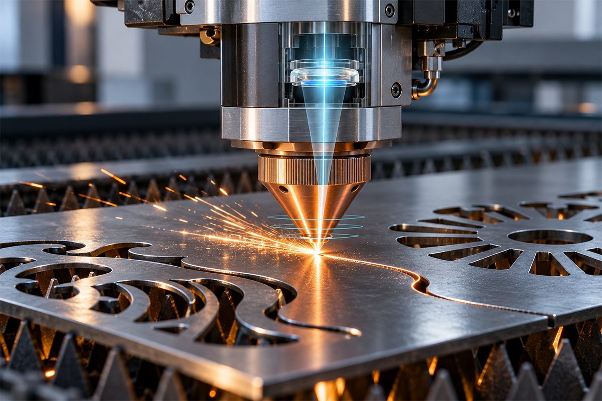
The Impact of Autofocus on Laser Cutting Precision
Laser cutting precision depends on more than laser power and machine positioning. The location of the laser’s focal point determines how energy is concentrated within the workpiece, influencing kerf width, edge quality, and cutting consistency. Even when the programmed cutting path remains accurate, an unsuitable focal position can produce dimensional variation, rough edges, or incomplete separation. Maintaining the appropriate focus is therefore essential for translating a digital design into a finished component that meets production requirements.
Autofocus helps control this variable by automatically positioning the laser focus according to the selected cutting parameters. Depending on the equipment, motorized optics adjust the focal position for different materials, thicknesses, and processing stages. The optimal focus may lie above, at, or below the material surface, depending on the application. Autofocus works alongside cutting-head height control, which maintains the nozzle’s distance from the workpiece; these functions serve different purposes but contribute together to stable processing. Some advanced systems also provide feedback that supports focus correction during operation.
For manufacturers, reliable focus positioning can support more consistent kerf geometry, cleaner cut surfaces, and repeatable results across production batches. Automatic adjustment also reduces manual setup and helps operators switch between cutting requirements more efficiently. These advantages are particularly relevant when producing detailed contours, small features, or components that must fit accurately during assembly. However, the improvement depends on selecting an appropriate focal position and coordinating it with the rest of the cutting process.
Autofocus does not independently determine a machine’s accuracy or guarantee defect-free parts. Its effectiveness depends on calibration, optical condition, mechanical performance, and suitable settings for laser power, cutting speed, and assist gas. Understanding these relationships provides a practical basis for evaluating its contribution. This article examines how autofocus works, how it influences cutting precision, and which operating conditions determine the benefits it can deliver.
Table of Contents
Understanding Focus and Precision in Laser Cutting
Focus determines how a laser beam’s energy is distributed where it interacts with the workpiece. Its influence extends beyond whether the beam can penetrate the material: it also affects kerf geometry, dimensional consistency, and the condition of the finished edge. Understanding autofocus therefore begins with understanding the beam itself, the location of its narrowest region, and the different measures used to evaluate cutting performance. These concepts explain why maintaining an appropriate focal position can improve production results while remaining only one part of achieving precise cuts.
How a Focused Laser Beam Cuts Material
The laser cutting system directs its beam through focusing optics, typically lenses or mirrors, which concentrate the light into a small area. Focusing increases the power delivered per unit area without increasing the laser’s total output power. When the workpiece absorbs sufficient energy, the material heats rapidly and undergoes the changes needed for removal. The response depends on the material, laser wavelength, exposure time, and cutting process.
In conventional metal cutting, the laser commonly melts material along the cutting front, while an assist-gas jet expels the molten material through the narrow opening known as the kerf. Nitrogen-assisted fusion cutting relies principally on laser energy to produce the melt. Oxygen-assisted cutting also uses heat released by oxidation to support material removal. Other laser cutting processes remove material predominantly through vaporization or ablation, so cutting does not always involve the same balance of melting and gas-assisted removal.
As the cutting head or workpiece moves, this localized interaction creates the programmed contour. Focus influences the width and shape of the interaction zone, but the resulting kerf also depends on cutting speed, gas delivery, material behavior, and heat flow. Consequently, beam diameter alone does not determine the finished dimensions of a component.
Beam Waist, Beam Divergence, and Depth of Focus
The beam waist is the region where a focused laser beam reaches its smallest diameter. The beam converges toward this region and expands after passing through it. For a given beam power and profile, the waist provides the greatest concentration of energy. It is a finite spot rather than an infinitely small point, which places practical limits on the detail the beam can produce.
Beam divergence describes how rapidly the beam spreads as it travels away from the waist. For a given wavelength and beam quality, producing a smaller waist generally increases divergence. A tightly focused beam can therefore provide intense, localized heating while changing diameter relatively quickly along the direction of propagation. Actual industrial beams may have more complex profiles than an ideal Gaussian beam, but the relationship between spot size and spreading remains important when selecting cutting optics.
Depth of focus describes the axial range around the waist over which the beam remains sufficiently concentrated for a specified purpose. In cutting, the useful range depends on how much variation in spot size and intensity the process can tolerate. A smaller waist generally brings a shorter depth of focus and greater sensitivity to focal-position errors. A longer depth of focus provides more tolerance, but does not automatically establish the maximum thickness that can be cut. Material absorption, available power, and melt removal also matter. Autofocus helps position this useful region; it does not inherently extend it.
Focal Position Relative to the Workpiece
Focal position describes where the beam waist lies relative to a reference on the workpiece, usually its upper surface. The waist may be positioned above the surface, at the surface, or within the material thickness. Moving it changes the beam diameter and intensity distribution at different depths, which can influence penetration, kerf taper, and the ability of cutting gas to remove molten material.
There is no single focal position that is optimal for every application. Material type, thickness, assist gas, beam characteristics, and the required edge condition all influence the choice. For example, some oxygen-assisted cutting processes use a focus near the upper surface, while certain nitrogen-assisted cutting applications benefit from positioning it farther into the thickness. These are process-dependent choices rather than universal rules. Machine-specific cutting data and representative trials provide the appropriate basis for setting the focus.
Surface height also matters. If a sheet is bowed or uneven, a stationary cutting head cannot maintain the same relationship between the optics and the material. Height control follows the surface to maintain nozzle clearance, while optical focus adjustment establishes the desired waist position relative to that surface. Systems may coordinate these functions, and some provide additional focus correction during processing. Their capabilities should be distinguished when assessing how effectively they maintain cutting conditions.
Focal Length Versus Focal Position
Focal length is an optical property that describes the focusing action of a lens or optical system. For incoming parallel light, it identifies the distance from the appropriate optical reference plane to the focus. It is distinct from nozzle clearance and from the depth of focus within a workpiece.
With the incoming beam diameter, wavelength, and beam quality held constant, a shorter focal length generally produces a smaller spot and a shorter depth of focus. A longer focal length generally produces a larger spot and a longer depth of focus. Selecting optics therefore involves balancing energy concentration, processing tolerance, and the requirements of the material.
Focal position, by comparison, concerns where the resulting waist is located relative to the material. Autofocus can shift this position by moving a focusing or collimating optical element without changing the nominal focal length of an individual lens. Some optical systems also adjust spot size or other beam characteristics, but these are additional capabilities. Describing every automatic focus adjustment as a change in focal length can therefore misrepresent how the cutting head operates.
Accuracy, Repeatability, and Edge Quality
Accuracy describes how closely a finished feature matches its intended dimensions or position. In laser cutting, this can include external dimensions, hole diameters, hole locations, and contour shape. Machine positioning contributes to accuracy, but finished-part accuracy also depends on kerf compensation, thermal effects, workpiece stability, and the cutting process.
Repeatability describes how consistently a system reproduces a result under the same conditions. A machine may repeatedly produce slightly undersized holes: the results can be highly repeatable while still failing the dimensional requirement. Similarly, an autofocus mechanism may consistently return to a programmed setting, yet produce an unsuitable focal position if its calibration or reference is incorrect. Consistency and correctness must therefore be assessed separately.
Edge quality concerns the physical condition of the cut surface. Relevant characteristics include roughness, striation patterns, burrs or dross, taper, oxidation, and thermal damage. A component can meet its overall dimensional tolerance while requiring edge finishing, or have a smooth edge while missing its specified dimensions. Focus influences these outcomes, but speed, nozzle condition, and assist-gas performance also contribute.
Autofocus should consequently be evaluated through finished-part measurements and edge inspection, alongside checks of the machine itself. Axis positioning tests characterize motion performance; they do not independently establish the quality of a cut component. The practical value of autofocus is its contribution to maintaining suitable processing conditions and reducing variation in the resulting parts.
Understanding focus requires separating the beam’s geometry, the optical system’s focal length, and the waist’s position relative to the workpiece. These factors govern how concentrated energy reaches the material and how sensitive cutting becomes to changes in height or setup. Autofocus helps establish and maintain an appropriate focal position. Its contribution to precision is best judged through dimensional accuracy, repeatability, and edge quality together, with suitable cutting parameters and a properly maintained machine supporting the result.
What Autofocus Means in Laser Cutting
Autofocus in laser cutting describes several functions that automate the positioning of the laser focus relative to the workpiece. Depending on the machine, it may involve setting the focus before a job, changing focal positions according to a cutting program, following variations in material height, or correcting focus drift during processing. These functions provide different levels of control. Understanding their differences helps explain how autofocus contributes to cutting precision and why machines advertised with autofocus may have substantially different capabilities.
The Basic Definition of Autofocus
At its broadest, autofocus means automatically establishing or adjusting the relationship between the laser’s focal region and the material being processed. The objective is to place the beam waist at a suitable location for the selected application. That location may be at the material surface, above it, or within its thickness, depending on the cutting process.
The mechanism varies with machine design. Some cutting heads use a motor to move a focusing or collimating optical element, shifting the beam waist along the beam axis. Other systems move the cutting head or worktable to establish the required distance between fixed optics and the workpiece. Consequently, automatic focusing does not necessarily mean changing the focal length of a lens. It often means relocating the focus relative to the material.
The word “automatic” also does not establish how the correct position is determined. A system may execute a value entered by an operator, retrieve a stored material recipe, measure the workpiece surface, or use feedback during cutting. Each approach reduces a different source of manual intervention, and each has a different relationship to process stability.
Automatic Focus Setting Before Cutting
Automatic focus setting before cutting establishes the starting focal position for a job. On a machine with motorized focusing optics, the operator typically selects the material, thickness, and cutting process. The controller then commands the focusing mechanism to the position specified by the applicable cutting data. This can reduce setup time and improve consistency when changing between established production recipes.
Other machines establish focus by locating the workpiece surface and automatically positioning the table or head. Depending on the equipment, surface detection may use a contact sensor, an ultrasonic sensor, or a light barrier. Software-based systems may instead calculate the required table position from the selected lens and entered material thickness. These methods automate the initial working distance, but they do not all measure the laser beam itself.
A distinction is necessary between moving to a reference position and verifying the actual optical focus. Homing a focusing motor establishes the mechanism’s coordinate reference; it does not independently confirm where the beam waist lies. Initial focus setting therefore depends on correct calibration and suitable process data. Likewise, a surface measurement taken at one location does not establish the height of every point on a bowed sheet.
Programmed Focal Adjustment
Programmed focal adjustment allows the controller to apply different focal positions at defined stages of a job. Instead of using one setting throughout the entire operation, the cutting program can command focus changes where the equipment supports them. For example, piercing and contour cutting may use different focal settings because they involve different material-removal conditions.
Focus settings can also be associated with processing layers or other programmed operations. The controller coordinates the selected focal position with the relevant cutting parameters, such as laser power, speed, gas pressure, and nozzle height. This allows established process knowledge to be applied consistently without requiring an operator to reposition the focusing mechanism manually between stages.
Programmed adjustment follows predetermined instructions. A change in focus during cutting does not, by itself, demonstrate that the machine has detected a problem or identified a better setting. Even when a motor encoder confirms that the focusing mechanism reached its commanded position, that feedback concerns mechanical movement. It does not necessarily measure the actual beam waist or evaluate the resulting cut edge. The precision benefit comes from executing appropriate settings reliably and at the correct point in the process.
Automatic Height Tracking
Automatic height tracking maintains a specified distance between the cutting head’s nozzle and the workpiece as the head travels. In many metal-cutting systems, capacitive sensing detects changes in the relationship between the nozzle and the conductive material. The controller uses this information to move the head vertically and maintain the required clearance.
Height tracking is valuable when sheets have gradual waviness, distortion, or elevation changes. With a stable optical configuration, maintaining nozzle clearance also helps preserve the intended relationship between the beam waist and the local material surface. This supports more consistent cutting conditions across a workpiece. However, the result depends on sensor performance, calibration, and the ability of the machine’s vertical axis to follow the surface.
Height tracking and optical focus adjustment control different quantities. Height tracking regulates nozzle clearance, while optical adjustment changes the waist’s position relative to the head. A machine can therefore follow a sheet accurately while using an unsuitable optical focus offset. Similarly, keeping the nozzle gap constant cannot independently correct a focus shift caused by changes within the optical system.
For this reason, automatic height tracking should be understood as a function that supports focus stability. Its presence alone does not establish that a machine measures or adaptively corrects the optical focus during cutting.
Adaptive Focus Control During Processing
Adaptive focus control adjusts focus in response to changing operating conditions. Depending on the implementation, it may use optical measurements, other operating signals, or a compensation model to determine the necessary correction. Its purpose is to address variations that a fixed setting or predetermined sequence cannot fully accommodate.
One application is compensation for focus drift as the cutting optics warm during operation. Changes in the optical system can move the actual focal position even when the focusing mechanism remains at the same commanded coordinate. Systems designed for focus-shift compensation adjust the mechanism to help preserve the intended focal position during processing. This capability is distinct from simply moving rapidly between stored settings.
Some implementations use sensors within the cutting head to monitor beam characteristics and support focal-position correction. In a feedback-based arrangement, the controller uses measured information to identify a departure from the target condition and commands an adjustment. This provides a closer connection between the operating beam and the commanded correction than mechanism-position feedback alone.
Adaptive compensation should also be distinguished from automatic process optimization. Maintaining a selected focal position does not necessarily mean the machine independently discovers the best focus for an unfamiliar material. Likewise, a monitoring system that changes cutting speed or detects incomplete penetration may have no authority to adjust focus. The relevant capability is whether operating information actually influences focal control, what disturbances it can address, and how reliably it maintains the required condition.
Autofocus can automate initial setup, execute programmed focal changes, support surface following, or compensate for changes during processing. These capabilities contribute to precision in different ways: setup automation improves consistency, programmed adjustment applies appropriate settings, height tracking preserves clearance, and adaptive control addresses supported disturbances. Evaluating autofocus therefore requires understanding what the machine moves, what information it uses, and when it makes corrections. Its practical value depends on maintaining a suitable focus through the conditions encountered in production.
Main Components and Operating Principles of Autofocus Systems
An autofocus system combines sensing, positioning mechanisms, control electronics, and software to establish the required relationship between the laser focus and the workpiece. Its operation depends on translating reliable position information into coordinated movement of the optics, cutting head, or worktable. Some systems perform this task only before cutting, while others maintain surface clearance or correct focus during processing. Understanding these components helps explain how autofocus supports precision and where measurement errors, mechanical limitations, or control delays can affect the result.
Sensors Used to Establish the Workpiece Position
Workpiece-position sensors identify the material surface or measure its distance from a reference point. The controller combines this information with optical calibration and the selected process settings to establish the intended focal position. These sensors generally measure the workpiece’s location rather than directly locating the laser beam waist.
Capacitive Distance Sensors
Capacitive distance sensing is widely used for height control in metal laser cutting. The nozzle acts as a sensing electrode, and the electrical capacitance between it and the conductive workpiece changes with their separation. Calibrated electronics interpret this signal as a distance measurement, allowing the height controller to command vertical movement.
This arrangement supports continuous, noncontact surface following. However, the measurement depends on the condition and geometry of the sensing arrangement. Nozzle changes, contamination, temperature drift, and nearby sheet edges can affect the signal. Calibration and suitable signal processing help the controller distinguish useful height information from disturbances. Capacitive height control maintains nozzle clearance; optical focus adjustment remains a separate function.
Optical Distance Sensors
Optical distance sensors use light to establish surface position. Depending on the design, measurement may rely on laser triangulation, chromatic confocal sensing, or another optical principle. These methods can provide noncontact measurements where electrical conductivity is unsuitable for capacitive sensing. Some arrangements measure from beside the processing head, while others integrate measurement into the optical path.
Performance depends on matching the sensor to the surface and operating environment. Reflectivity, transparency, texture, inclination, and interference from surrounding light can influence measurement reliability. Protective arrangements must also preserve a clear measurement path around fumes and contamination. An optical distance sensor that measures the material surface should therefore be distinguished from an optical monitoring system that examines the processing beam itself.
Contact and Ultrasonic Sensors
Contact sensors establish a reference when a probe or sensing element touches the material. In some laser cutting systems, the worktable rises until the workpiece triggers the sensor. The controller then uses the calibrated relationship between that trigger position and the optics to establish focus. This approach can simplify initial setup, provided the material remains stable during contact.
Ultrasonic sensors locate the surface using reflected sound. They offer noncontact sensing without depending on the material’s electrical conductivity or optical color. Their suitability depends on obtaining a reliable echo within the sensor’s working range. Surface orientation, sound absorption, and environmental conditions can influence that echo.
Contact and ultrasonic arrangements are used for automatic setup on certain laser cutters and engravers. Their presence does not necessarily establish continuous tracking capability: a machine may measure the surface once, position the table, and retain that setting throughout the job.
Focus Adjustment Mechanisms
In many industrial cutting heads, a motor-driven mechanism moves a focusing or collimating optical element along the beam axis. Moving the focusing optics changes where the beam converges, while moving a collimating element changes the beam entering the focusing assembly and consequently shifts the waist. This allows focal adjustment within the head without requiring the same change in nozzle clearance.
The positioning assembly includes a drive, mechanical guidance, and a means of establishing its reference position. Where fitted, an encoder provides feedback about mechanism position. Mechanical stiffness, alignment, wear, and repeatability influence how reliably a command produces the intended movement. However, confirming the carriage position does not independently verify the actual optical focus.
Other systems establish focus by moving the entire head or worktable relative to fixed optics. This changes the distance between the material and the optical assembly. The appropriate mechanism depends on whether the machine performs initial focusing, continuous surface following, internal optical adjustment, or a combination of these functions.
CNC and Software Integration
The CNC coordinates focal settings with the cutting program. Software may store focus positions alongside material thickness, cutting speed, laser power, gas settings, and nozzle height. Where supported, separate settings can be assigned to piercing, contour cutting, and other processing stages. Reliable integration ensures that these settings change at the intended point in the operation.
Fast control tasks may be handled by dedicated electronics rather than by the main CNC alone. A height controller interprets distance measurements and commands the vertical axis, while the focusing drive positions the optics. Industrial communication links exchange commands, status information, and diagnostic data between these components. Their timing affects how promptly the complete system reacts.
Software also manages calibration values, movement limits, sensor status, and fault handling. Advanced configurations may incorporate beam-monitoring information or focus-shift compensation. These capabilities depend on the installed hardware and control functions; ordinary motorized focus positioning does not automatically provide adaptive optical feedback.
A Typical Autofocus Operating Sequence
A representative sequence begins with loading the cutting program and selecting the appropriate material and process data. The machine establishes the required axis references and uses valid calibration information for the focusing mechanism and surface sensor. Homing establishes a mechanical coordinate reference, while focus calibration establishes how commanded positions relate to the optical processing condition.
The head or table then approaches the measurement position, and the selected sensor establishes the workpiece surface reference. The controller combines this reference with the required working distance and focal offset. It commands the optics, head, or table to the corresponding position and allows the movement to settle before the relevant processing stage begins.
For machines with programmed focal adjustment, piercing may use one setting and contour cutting another. The controller coordinates these transitions with laser output, gas delivery, and head movement. Machines equipped with continuous height tracking then maintain the selected nozzle clearance as the cutting path progresses.
If adaptive focus correction is installed, an additional control function compensates for supported changes during processing. After cutting, the head can retract for travel and repeat the appropriate positioning sequence at the next location. This is a general operating pattern: machines that provide only initial autofocus do not necessarily perform continuous tracking or adaptive correction.
Response Time and Tracking Performance
Response time includes more than how quickly a sensor produces a reading. Measurement acquisition, filtering, communication, controller calculations, motor acceleration, and mechanical settling all contribute to the delay between detecting a change and completing a correction. A high sensor sampling rate therefore does not, by itself, demonstrate equally fast or accurate movement.
Focus-positioning performance and surface-tracking performance should also be assessed separately. Internal optics must reach commanded focal settings accurately and settle within the time available. Height tracking must move the head smoothly enough to follow the material while maintaining clearance. The two functions involve different moving masses, travel requirements, and disturbances.
Tracking becomes more demanding as cutting speed increases or surface height changes more sharply. If the vertical axis cannot follow quickly enough, clearance errors develop even when the distance measurement is accurate. Increasing control responsiveness can reduce lag, but excessive gain can cause oscillation. Stronger filtering can suppress vibration-related disturbances while slowing the response. Effective tuning balances these effects.
Useful performance measures include focus-position repeatability, movement and settling time, and dynamic tracking error under defined operating conditions. Static sensor resolution should be considered alongside these measures rather than treated as a guarantee of finished-part precision. Representative cutting results establish whether the combined sensing, mechanics, and controls maintain suitable conditions in production.
Autofocus performance depends on the complete chain from surface detection to controlled movement. Sensors establish workpiece position, adjustment mechanisms place the focal region, and CNC integration coordinates these actions with cutting conditions. Calibration connects measured and commanded positions to the intended process, while response time determines how effectively the system handles changes. Accurate sensing, repeatable mechanics, and stable control must work together for autofocus to support consistent dimensions and edge quality.
How Autofocus Affects Laser Cutting Precision
Autofocus affects laser cutting precision by helping establish and maintain an appropriate focal position for the material and process. Stable focus supports consistent energy concentration and material removal, which influence finished dimensions, kerf geometry, edge condition, and the reproduction of detail. The benefits depend on the system’s capabilities: initial focus setting reduces setup variation, while coordinated height tracking and adaptive focus correction address supported changes during processing. These functions contribute to precision alongside suitable cutting parameters, accurate machine motion, and reliable workpiece positioning.
More Consistent Dimensional Results
Finished dimensions depend on both the programmed cutting path and the amount of material removed around that path. If focus changes cause the kerf to widen or narrow while the programmed compensation remains unchanged, the finished boundary can shift. A wider kerf can remove additional material from an external contour or enlarge an internal opening, affecting fit even when the machine follows its commanded path correctly.
By reducing unwanted focal variation, autofocus can help keep the material-removal zone more consistent. This supports predictable dimensions in profiles, slots, holes, and mating features. Its contribution is particularly relevant when focus-related variation would otherwise consume a significant portion of the available tolerance. Achieving the specified dimensions still requires correct kerf compensation, calibrated machine positioning, and stable workpiece support. Autofocus helps preserve suitable processing conditions within that wider system.
Better Control of Kerf Width
Kerf width is influenced by the beam diameter and energy distribution where the laser interacts with the material. Changes in focal position alter these conditions at the upper surface and through the thickness. Maintaining an appropriate focus therefore helps reduce unintended changes in the width of the cut, making the process more predictable along a contour and between components.
The objective is a suitable, repeatable kerf for the application. Fine features may require a narrow opening, while thicker metal cutting also requires sufficient space for assist gas to enter and molten material to escape. The focal setting must support both energy delivery and material removal. Autofocus can repeatedly apply that setting, but kerf width also responds to speed, power, gas conditions, and material properties. Measurements from representative cuts remain necessary when establishing compensation values.
Reduced Variation in Cut Taper
Cut taper occurs when the cut walls are inclined, producing different dimensions at the upper and lower surfaces. The beam’s changing diameter through the thickness contributes to the conditions that form those walls. Focal position also affects the geometry of the opening through which cutting gas and molten material travel, linking optical conditions with the material-removal process. Experimental work on stainless steel has demonstrated relationships between focal position, upper and lower kerf geometry, and cut-edge roughness.
Autofocus can help maintain a selected focal relationship and thereby reduce variation in taper between locations or parts. This can improve consistency where components must fit through their full thickness rather than only at one surface. The achievable taper still depends on beam characteristics, thickness, gas flow, and the selected cutting regime. An appropriate focus can improve wall geometry, but maintaining focus alone does not establish perfectly perpendicular walls under every condition.
More Consistent Edge Quality
Focus influences how energy reaches the cutting front and how material melts and leaves the kerf. When focus drifts outside a suitable process range, the result may include changing roughness, uneven striations, intermittent dross, or incomplete separation. Research on laser cutting of Hardox steel identified focal position as a significant factor affecting both surface roughness and kerf width, illustrating why focus stability matters to the finished edge.
Autofocus can help preserve an established edge finish by reducing this source of process variation. More uniform edges can simplify inspection, assembly, and subsequent finishing. Their condition also depends on nozzle alignment, gas delivery, cutting speed, optical cleanliness, and material consistency. Oxidation, for example, is strongly connected to the cutting atmosphere. Reliable focus supports edge quality most effectively when these other conditions remain within the validated operating range.
Improved Reproduction of Small Features
Small holes, narrow slots, intricate contours, and thin connecting webs are particularly sensitive to changes in the material-removal zone. A width variation that has little effect on a large profile can substantially change a small opening or weaken a narrow section. Maintaining the intended focus helps preserve the localized interaction required to reproduce these details consistently. Precision cutting systems accordingly combine suitable optics with stable distance control to support fine contours and controlled gap widths.
Autofocus helps preserve the detail available from the selected laser and optical system. The minimum practical feature size also depends on spot diameter, beam quality, material thickness, piercing behavior, and machine dynamics. Tight contours require coordinated motion and energy delivery, especially where the head slows down. Suitable lead-ins, piercing locations, and corner parameters therefore remain important. Stable focus makes those settings more repeatable, helping small features retain their intended shape and dimensions.
Control of Heat Input and Thermal Effects
Focal position influences the concentration and spatial distribution of laser energy. Adjusting focus does not inherently change the laser’s total output power, but it can change how that energy interacts with the material. An appropriate setting supports efficient removal in the intended cutting region and helps maintain the process conditions used to control thermal damage.
The practical benefit is maintaining efficient separation without unnecessary compensating changes, such as excessive slowing or repeated passes caused by unsuitable focus. However, heat accumulation also depends strongly on power, exposure time, cutting speed, material conductivity, and the sequence of nearby cuts. Corners and closely spaced features can accumulate heat even with stable focus. Autofocus must therefore operate alongside suitable motion, power modulation, and toolpath planning.
Focus also interacts with other parameters in determining the heat-affected zone. Experimental research on nickel-alloy cutting, for example, evaluated focal position together with power, speed, and gas pressure when assessing thermal and geometric results. This supports treating focus as part of a coordinated process setting. Where heating causes sheet distortion, height tracking may help follow the changing surface, while control of the distortion itself requires management of the overall thermal process.
Greater Repeatability Across Production Runs
Automatic focus positioning reduces reliance on manually reproducing a setting each time a job is prepared. Stored recipes can apply established focal positions consistently across operators, shifts, and repeat orders. Where supported, the controller can also reproduce different settings for piercing and cutting stages. This helps turn a successful setup into a repeatable production process.
Continuous production introduces additional changes. Surface height can vary between sheets, and optical heating can shift the actual focus during operation. Coordinated height control and dedicated focus-shift compensation can address their respective disturbances, helping maintain processing conditions as production continues. These capabilities extend beyond initial automatic positioning and should be assessed separately.
Repeatable settings deliver the greatest value when they are calibrated and produce acceptable parts. A machine can consistently reproduce an unsuitable focal position, so production verification should connect the stored recipe with measured dimensions and edge condition. With that connection established, autofocus helps reduce setup-related variation and supports dependable results across successive runs.
Autofocus supports precision by reducing unwanted variation in the focal conditions that govern energy delivery and material removal. Its benefits can include more consistent dimensions, controlled kerf width, reduced taper variation, uniform edges, and reliable reproduction of small features. It also contributes to thermal-process consistency and repeatability across production runs. The improvement depends on selecting an appropriate focal setting and maintaining it through the relevant operating conditions, with machine motion, gas delivery, calibration, and cutting parameters working together.
Material and Thickness Considerations
The effect of autofocus on cutting precision depends on how the material absorbs laser energy, conducts heat, and responds to the cutting gas. Thickness introduces further requirements for penetration, kerf geometry, and removal of molten material. Consequently, a focal setting that produces accurate results in one application may perform poorly in another. Autofocus provides the greatest benefit when it applies validated settings for the actual material, thickness, laser configuration, and required edge condition. Sensor compatibility also matters, particularly when moving between conductive metals and nonmetallic materials.
Carbon Steel
Carbon steel is commonly cut with oxygen, which supports the process through an exothermic oxidation reaction. Nitrogen, compressed air, and selected gas mixtures are also used in suitable applications. These processes establish different conditions at the cutting front, so their focal settings should be treated as separate recipes. Changing the assist gas can require coordinated changes in focus, power, speed, pressure, and nozzle configuration.
Some oxygen-assisted cutting processes use a focal position near the upper surface. Other beam configurations and cutting conditions require different positions, making a universal surface-focus rule inappropriate. Autofocus helps reproduce the selected setting and, where supported, apply separate focal positions for piercing and contour cutting. Combined with height tracking, it can also help preserve the intended relationship between the focus and a gradually uneven sheet.
Material condition remains significant. Grade, mill scale, rust, coatings, and surface contamination can affect process stability even when focus is correctly maintained. Thick carbon steel also requires coordinated control of the oxidation reaction and heat accumulation. Reliable autofocus supports that process, while representative trials establish whether the selected settings deliver acceptable dimensions, taper, and edge condition on the stock being used.
Stainless Steel
Stainless steel is frequently cut with nitrogen when a low-oxidation edge is required. In this process, laser energy melts the material, and the gas jet removes it from the kerf. Focus must therefore support both sufficient energy delivery and an opening through which the gas can effectively clear molten metal. Gas purity and delivery conditions also influence the finished edge.
For some nitrogen-assisted applications, positioning the focus within the material improves the balance between penetration, kerf geometry, and melt removal. Research on fiber laser cutting of stainless steel and aluminum has demonstrated that suitable internal focal positions can improve surface roughness under particular processing conditions. The appropriate depth remains specific to the equipment and parameter combination.
Autofocus can help reproduce these settings and reduce variation between sheets or production runs. As thickness increases, inspection should consider the lower edge and full cut-wall profile, since an acceptable upper surface can coexist with bottom-edge dross or excessive taper. Protective films and surface finishes should also be included when validating the complete piercing, sensing, and cutting sequence.
Aluminum, Copper, and Brass
Aluminum, copper, and brass require attention to their optical and thermal properties. Aluminum and copper readily conduct heat away from the interaction zone, while reflectivity can make establishing a stable cut more demanding. Suitable near-infrared laser systems can process highly reflective metals, but sufficient energy concentration and an appropriate process configuration are essential. Autofocus helps maintain the selected energy distribution without changing the material’s underlying absorption characteristics.
For aluminum, focal position must be coordinated with speed, power, assist gas, and nozzle geometry to achieve reliable penetration and melt removal. The best setting can differ between alloy grades, thicknesses, and surface conditions. Maintaining an established focal position can reduce process variation, but a setting developed for stainless steel should be validated before being applied to aluminum.
Copper and brass similarly require material-specific cutting and piercing data. Their different compositions and thermal behavior mean that they should not automatically share one recipe. The laser source and cutting head must also be suitable for reflected radiation. Autofocus contributes to process consistency, while the equipment’s approved configuration and reflection-management provisions determine its suitability for these materials.
For all three materials, evaluation should include complete separation, bottom-edge condition, dimensional consistency, and the transition from piercing to cutting. A successful initial penetration alone provides limited evidence of stable production performance.
Acrylic, Wood, and Other Suitable Nonmetals
Acrylic, wood products, paper, cardboard, and selected textiles are commonly processed with carbon dioxide lasers. Their interaction with the beam differs from conventional metal cutting, and their autofocus arrangements may use table positioning, contact sensing, ultrasonic measurement, or compatible optical sensors. Standard capacitive nozzle tracking intended for conductive metal requires a different sensing approach for ordinary nonconductive surfaces.
For acrylic, focus influences kerf shape, taper, and edge appearance. As thickness increases, a longer focal length may provide a more suitable depth of focus, while a validated focal offset can position the useful beam region within the material. Cast and extruded acrylic can require different processing conditions. Autofocus helps repeat the chosen setup, with lens selection, power, speed, and material quality contributing to the final result.
Transparent acrylic also requires suitable surface detection. Some light-barrier arrangements are intended for opaque stock and may fail to establish the correct reference on clear material. A compatible sensor or an approved alternative focusing method is therefore important when assessing autofocus performance.
Wood introduces variation through density, grain, moisture, resin, and, in engineered products, adhesive composition. Autofocus can address positioning variation within its capabilities, but these material differences can still produce uneven penetration or changing edge darkness. Flat stock, suitable air assist, and consistent laser-compatible wood products help make the focal setting more reproducible.
Other nonmetals should be assessed by their full composition, including coatings, adhesives, and additives. Use materials confirmed as suitable for the particular laser process. PVC and other unsuitable halogen-containing materials should be excluded; focusing capability does not establish material compatibility.
Thin Sheets Versus Thick Plates
The distinction between thin and thick material is relative to the laser, material, and required quality. A thickness that is straightforward for one configuration may approach the practical limit of another. Autofocus should therefore be evaluated against the intended production range rather than a universal thickness category.
Thin sheets often permit high cutting speeds and fine features. When small focused spots are used, the accompanying shorter depth of focus can make the process sensitive to surface-height errors. Thin material can also bow or vibrate under thermal loading and assist-gas forces. Stable support and suitably tuned height tracking help preserve clearance without allowing the controller to amplify disturbances.
Thick plates place greater demands on energy delivery through the depth and removal of molten material. Focal position influences the relationship between the upper and lower kerf, while beam characteristics and gas flow affect taper and bottom-edge quality. A suitable optical configuration may provide a longer useful focal region, and separate piercing and cutting settings may be beneficial. Autofocus positions that region; it does not inherently extend the optical depth of focus or establish additional cutting capacity.
Thickness measurement should also be distinguished from surface-height measurement. A sensor locating the upper surface does not necessarily measure the distance to the lower surface. Automatic adaptation to changing thickness requires appropriate thickness information, programmed data, or additional measurement capability.
Material and thickness determine which focal settings, sensors, and control functions are useful. Carbon steel requires coordination with the selected gas-assisted process; stainless steel and nonferrous metals require suitable energy delivery and melt removal; nonmetals require compatible lasers, materials, and surface-detection methods. Thin stock emphasizes stable positioning and dynamic response, while thick stock demands control through the full cut depth. Autofocus supports precision most effectively when it reproduces validated conditions for the actual application.
Interaction Between Autofocus and Other Cutting Parameters
Autofocus operates within a coordinated cutting process. Focal position influences energy concentration and kerf geometry, while laser power, speed, gas delivery, optics, and machine movement determine how those conditions produce a finished cut. Changing one parameter can alter the requirements for the others. The precision benefit of autofocus therefore depends on applying suitable combinations of settings and coordinating their transitions throughout the job. Automatic positioning makes established settings more repeatable, while appropriate process development determines which settings should be used.
Laser Power and Cutting Speed
Laser power determines the rate at which the source supplies energy, while focal position influences how that energy is distributed at the cutting front. Cutting speed determines how long the beam interacts with each region of material. Together, these parameters affect penetration, melt formation, kerf width, and heat transfer into the surrounding workpiece. A suitable power setting can still produce poor results if the focus or speed is inappropriate.
Autofocus helps maintain the energy distribution associated with an established power-and-speed combination. This can reduce variation caused by an incorrectly reproduced setup or unsupported changes during processing. However, a shift in focus may alter the balance between energy absorption and material removal, so a substantial focal adjustment can require reassessment of speed and power. Increasing power to overcome unsuitable focus may also change kerf geometry and thermal effects.
The aim is to maintain a range of conditions that provides complete separation with acceptable dimensions and edge quality. Research on stainless steel and aluminum cutting illustrates that successful results depend on combinations of power, speed, focal position, and gas pressure. Autofocus helps reproduce the focal component of that combination; any automatic adjustment of the other parameters requires additional control functions.
Assist Gas, Nozzle Design, and Standoff Distance
Assist gas removes molten material and, depending on the gas, may also participate in the cutting reaction. Oxygen-assisted cutting gains heat from oxidation, while nitrogen-assisted fusion cutting relies primarily on laser energy to melt the material. These differences affect the relationship between focus, kerf geometry, and gas delivery. A focal setting developed for one gas should therefore be reassessed before being used with another.
Nozzle diameter, internal geometry, condition, and alignment influence how the gas reaches the cutting front. Focus adjustment changes the beam geometry within the material and can also change beam clearance through the nozzle. The selected nozzle must accommodate the approved optical settings while delivering a suitable gas jet. Misalignment or nozzle damage can produce direction-dependent cutting problems even when the focal position is correct.
Standoff distance is the gap between the nozzle and workpiece. It affects gas delivery and must be coordinated with the desired focal position. On heads with internal optical adjustment, focus can change while nozzle clearance remains constant. Moving the entire head changes both relationships unless the controller compensates appropriately. Height tracking and focus positioning consequently serve separate but connected purposes. A stable gap supports consistent gas conditions, while the optical setting establishes the intended focal depth.
Piercing and the Transition to Cutting
Piercing creates the initial opening before the machine begins following the cutting contour. Its conditions differ from those of an established through-cut: the material initially has no open kerf through which molten metal can escape. Focus, head height, laser output, pulse settings, gas delivery, and duration may therefore require a distinct piercing recipe.
Where supported, autofocus allows programmed focal changes between piercing stages and the subsequent cutting operation. Multistage strategies can coordinate these changes with other parameters as penetration develops. Some machines also use process monitoring to identify breakthrough or regulate piercing. That monitoring is an additional capability and should be distinguished from a focusing mechanism that simply executes programmed positions.
The transition to contour cutting requires appropriate timing. Focus movement, nozzle height, gas conditions, laser output, and feed motion must reach their validated relationship before the precision portion of the contour is produced. Depending on the machine and process, this may involve a controlled transition or a positioning interval.
Lead-ins help establish stable cutting away from the finished boundary. They also reduce the influence of starting-speed variation and the piercing location on the final edge. Accurate cutting focus cannot recover material already removed by an oversized piercing crater, making the complete start sequence important to dimensional quality.
Beam Quality and Optical Configuration
The available focal spot and depth of focus depend on the source beam and optical system. Relevant factors include wavelength, beam quality, incoming beam diameter, focal lengths, and optical magnification. Autofocus positions the resulting focal region relative to the material, but its adjustment range does not independently establish the smallest achievable spot or longest useful depth of focus.
For a given wavelength and beam quality, a smaller waist generally brings greater divergence and a shorter depth of focus. This can support fine detail while increasing sensitivity to positioning errors. Other applications benefit from a different balance between spot size, usable focal range, and kerf geometry. Autofocus is most effective when the optical configuration already suits the required material thickness and feature size.
Some cutting heads provide variable magnification or other beam-adjustment functions alongside focal positioning. These capabilities can establish different conditions for piercing and cutting, but changing beam geometry may also require changes to power, speed, gas delivery, and kerf compensation. The same numerical focus command should therefore be interpreted within the calibration and configuration of the specific head.
Optical cleanliness and alignment remain part of this relationship. Contamination can reduce transmitted power, distort the beam, or introduce thermal changes. Adaptive focus correction may compensate for supported focal drift, while maintaining the intended beam distribution still requires serviceable optics and proper alignment.
Toolpaths and Motion Control
The actual cutting speed changes as the machine accelerates, approaches tight curves, and negotiates corners. These changes affect exposure time even when the programmed nominal speed remains unchanged. If laser output stays constant during substantial deceleration, local heat accumulation can increase, changing the kerf or producing excessive melting and dross. Stable focus must therefore be coordinated with appropriate power or pulse control through these regions.
Toolpath sequencing also influences the conditions autofocus encounters. Closely spaced cuts can accumulate heat, while releasing a component can alter its support and position. Suitable cutting order, lead-ins, cooling strategies, and microjoints help preserve stable processing conditions. Height tracking can follow supported surface changes, but workpiece restraint and cutting sequence remain important to controlling those changes.
Motion performance determines how effectively the machine follows both the contour and the surface. Vertical tracking must respond within the available speed and acceleration limits, while programmed optical changes must be synchronized with processing stages. Excessive lag can disturb clearance or focal relationships; overly aggressive tracking can introduce oscillation. Focus control therefore complements accurate axis motion and suitable controller tuning.
Kerf compensation connects these process conditions back to finished dimensions. If a change in focus, optics, or cutting strategy alters the actual kerf, the existing toolpath offset may require verification. Consistent focus makes compensation more dependable, while measurements establish whether the finished contour matches the design.
Autofocus contributes to precision through its interaction with energy delivery, gas-assisted removal, optical configuration, and machine movement. Power and speed establish exposure conditions; nozzle design and standoff govern gas delivery; piercing requires a coordinated transition; and toolpaths influence heat accumulation and support. Treating these settings as a validated combination allows autofocus to reproduce useful conditions consistently. Changes to that combination should be evaluated through complete cuts, dimensional measurements, and edge inspection.
Autofocus in Challenging Cutting Applications
Challenging cutting applications place greater demands on maintaining the relationship between the laser focus and the workpiece. Surface distortion, rotating profiles, inclined cutting angles, and prolonged thermal loading can change the conditions encountered during a job. Autofocus helps establish suitable focal positions, while coordinated surface tracking and machine motion preserve the required working relationship. Its contribution depends on the installed capabilities: initial automatic positioning, programmed optical adjustment, height following, and adaptive focus correction address different sources of variation.
Warped and Uneven Sheets
Sheets may arrive bowed, rest unevenly on the cutting bed, or deform as heat and residual stresses redistribute during cutting. As surface height changes, a head operating at a fixed elevation experiences changes in nozzle clearance and focal position relative to the material. These variations can affect energy concentration, gas delivery, penetration, and kerf geometry.
Coordinated height tracking helps the head follow gradual surface changes while maintaining the selected nozzle clearance. With stable optical calibration, this also helps preserve the intended focal depth relative to the local surface. Internal focus adjustment establishes the optical offset required by the cutting recipe. Together, these functions support more uniform conditions across material that is moderately uneven.
Tracking performance depends on the shape of the distortion and the speed at which the head encounters it. Gradual waviness is generally easier to follow than an abrupt height change. Thin sheets may also vibrate under assist-gas forces, producing disturbances that require suitable filtering and controller tuning. Excessive control gain can cause oscillation, while stronger filtering can delay the response.
Workpiece preparation remains important. Suitable support and restraint reduce movement and keep surface variations within the machine’s operating capability. Maintaining focus addresses local cutting conditions, while dimensional changes caused by in-plane movement or severe distortion require additional measures. Similarly, raised cutouts and unsupported sections require appropriate cutting sequences and part-retention strategies.
Tube and Profile Cutting
Tube cutting combines longitudinal movement, rotation, and cutting-head motion. Round tubes may have ovality or bowing, while rectangular and shaped profiles present changing faces, corner radii, and surface elevations. Maintaining a suitable nozzle distance throughout these movements helps preserve gas delivery and the intended relationship between the focus and the tube wall.
Motorized focal adjustment allows established settings to be applied for the material, wall thickness, and processing stage. Surface tracking manages supported changes in the position of the wall as the tube moves. The controller must coordinate these functions with rotation and feed motion, particularly around profile corners and small features where movement conditions change rapidly.
Focus control also works alongside geometric measurement. Dedicated systems may scan the tube cross-section, compensate for raw-material tolerances, or detect and align the weld seam. These functions help locate the cutting program correctly on the actual profile. Autofocus then supports the optical conditions at that location. Maintaining the correct focal depth alone cannot establish the intended hole position when the tube’s shape or angular alignment differs from the assumed geometry.
Accurate results consequently depend on stable clamping, appropriate intermediate supports, and reliable coordination of the machine axes. Wall-thickness information must also come from the appropriate material data or measurement system; detecting the outer surface does not independently establish the wall thickness. Validation should consider feature position, cut-wall quality, and fit between connecting profiles.
Three-Dimensional and Bevel Cutting
Three-dimensional cutting follows formed or curved components whose surface position and orientation change along the contour. The machine must coordinate the head’s working position, orientation, and clearance while maintaining suitable focal conditions. Depending on the equipment, this can combine programmed geometry with surface sensing and local correction. Dedicated cutting heads use compact mechanisms and distance-control systems to support these dynamic movements.
Bevel cutting adds another interaction. Tilting the beam changes its path through the material and the way the beam and gas jet meet the surface. For a flat plate, an inclined path passes through more material than a perpendicular path. The appropriate combination of focus, speed, power, gas delivery, and nozzle geometry can therefore change with bevel angle. Settings validated for a straight cut should be reassessed for the inclined application.
The controller must interpret focal position and clearance using the local surface geometry and beam direction. Sensor behavior, nozzle clearance, and head accessibility also need to suit the intended angles. A tracking arrangement developed for flat, perpendicular cutting may require different calibration or dedicated hardware for inclined surfaces. Automatic focal adjustment is most useful when integrated with these geometric and process requirements.
The precision of the finished bevel also depends on axis calibration, the head’s working-point calibration, component location, and fixture stability. Focus stability supports consistent material removal and edge condition, while these other factors establish the bevel’s angle and location. Inspection should therefore consider the complete edge geometry, including the remaining land where relevant to weld preparation.
Dense Nesting and Long Cutting Cycles
Dense nests place many cuts close together, increasing the possibility of localized heat accumulation and changing workpiece support as material is removed. Expansion, bending, and stress release can alter surface height during the job. Research on densely cut stainless sheet has demonstrated that cutting sequence influences thermal deformation, illustrating why initial sheet flatness alone does not establish stable conditions throughout a nest.
Height tracking can help maintain clearance as supported surface changes develop, while autofocus preserves the selected optical setting. Cutting order, spacing, cooling strategies, and part retention help manage the underlying disturbances. Sequencing cuts across different areas can reduce concentrated thermal loading; nesting software may provide dedicated strategies for dense patterns. Maintaining focus supports these measures, while controlling sheet movement and heat accumulation remains essential to dimensional accuracy.
Long cycles also expose the cutting optics to changing thermal conditions. The actual focus may drift as the optical assembly warms, even when the mechanism remains at the same commanded position. Systems equipped with suitable focus-shift compensation can correct for drift and help maintain processing conditions as production continues. This capability is separate from simply repeating a stored focus command.
Sustained precision also depends on cooling stability, sensor condition, optical cleanliness, and nozzle performance. Evaluating parts from different sheet locations and different stages of a long cycle helps establish whether the complete system maintains dimensions and edge quality. A successful first component provides only part of that evidence.
Autofocus supports challenging applications by maintaining suitable optical conditions as geometry and operating conditions change. Warped sheets require responsive surface following; tubes require coordinated rotation, positioning, and profile correction; three-dimensional and bevel cuts require accurate orientation and angle-specific settings. Dense nesting and long cycles add thermal deformation and optical drift. Reliable precision comes from integrating focus control with appropriate sensing, motion, support, calibration, and process planning.
Manual Focusing Versus Autofocus
Manual focusing and autofocus both aim to position the laser’s focal region appropriately relative to the workpiece. Their main differences concern how the setting is established, reproduced, and adjusted as production conditions change. Carefully performed manual focusing can produce precise cuts, while autofocus can improve setup consistency and support programmed or adaptive adjustments. A meaningful comparison therefore considers finished-part accuracy, variation across repeated setups, and performance throughout representative production conditions.
Capabilities and Limitations of Manual Focusing
Manual focusing requires an operator to establish the appropriate optical setting or working distance. Depending on the machine, this may involve a calibrated focus gauge, a mechanical adjustment scale, or manual positioning of the head or worktable. The method must suit the installed optics and account for any required focal offset into or above the material. Manufacturers provide manual focusing tools for specific optical configurations, illustrating that manual adjustment can be a controlled procedure.
On flat, consistently supported material, a trained operator can establish a suitable focal position and verify it through representative cuts. For jobs using stable conditions and few setting changes, manual focusing may provide satisfactory dimensional accuracy and edge quality. The focusing method alone does not determine the beam’s optical capabilities. Comparable results are possible when manual and automatic methods establish the same actual focal conditions within an otherwise equivalent process.
The practical limitation is the effort required to reproduce and verify the setting. Results depend on the condition of the reference tool, the adjustment mechanism, the chosen measurement location, and the operator’s procedure. Frequent material or thickness changes increase the number of adjustments and opportunities for setup variation. Manually established optical settings also offer limited flexibility for changing focus between processing stages during a continuous job.
Manual optical focusing should be distinguished from manual height control. A cutting head can have a manually established focus offset while automatically maintaining nozzle clearance through a separate height-sensing system. Such a configuration can follow supported surface variations even though its optical focus setting remains fixed. The presence of automatic height following therefore needs to be identified separately when comparing focusing methods.
Practical Advantages of Autofocus
Autofocus reduces the manual work involved in establishing and reproducing focal positions. Motorized systems can apply stored settings for different materials, thicknesses, and processing stages, while other arrangements automatically establish the working distance from a surface measurement or entered thickness. This is particularly useful when production involves frequent changeovers or repeated orders.
Programmed focal adjustment also allows supported machines to use different settings for piercing and contour cutting. The controller can coordinate these changes with laser output, gas delivery, nozzle height, and feed motion. This makes an established process sequence easier to repeat without requiring a manual optical adjustment between stages.
Additional benefits depend on the installed control functions. Coordinated height tracking can help preserve the focus-to-surface relationship as the head follows uneven stock. Dedicated adaptive focus systems can correct supported changes in the actual optical focus during operation. These capabilities can improve consistency over changing conditions, but an autofocus system that only positions the mechanism before cutting provides a different level of control.
Autofocus also shifts operator work toward selecting and maintaining validated recipes, checking calibration, and interpreting process results. Accurate automation requires reliable references and serviceable sensors, optics, and mechanics. A mechanism can repeatedly reach an unsuitable commanded setting, so repeatable movement must remain connected to verification of the finished cut.
Making a Fair Precision Comparison
A fair comparison begins by defining the functions being evaluated. Initial automatic focus setting, motorized changes during a program, automatic height tracking, and adaptive optical correction should be identified individually. If one configuration includes continuous surface following and the other does not, the results represent the combined difference in control capabilities. They cannot be attributed solely to manual versus motorized focus adjustment.
Where practical, use the same machine and optical configuration in both modes. Otherwise, document differences in laser source, beam characteristics, optics, machine motion, and sensing. Match the material grade, thickness, surface condition, support, nozzle, gas delivery, cutting program, and thermal conditions as closely as possible. Both methods should receive suitable calibration and process development, with skilled manual setup compared against correctly configured automation.
The test should distinguish the quality of one established setup from the ability to reproduce that setup. Cutting several parts without resetting focus evaluates stability within a run. Repeating the focusing procedure between trials evaluates setup repeatability. Including multiple operators or changeovers can reveal workflow-related variation, while longer trials can show whether performance changes as the machine and material warm.
Measurements should address the application’s actual requirements. Dimensional error, variation between parts, kerf width, taper, roughness, and dross provide different information. Measure equivalent features and surface locations using suitable instruments and consistent part-temperature conditions. Where applicable, an agreed thermal-cut quality specification such as ISO 9013 can provide a common classification basis. Report the distribution of results and the proportion meeting requirements, alongside any representative examples.
Setup time, adjustment frequency, scrap, and throughput should also be recorded, while remaining distinguishable from dimensional accuracy. Autofocus may produce similar best-part accuracy with fewer setup variations or less operator intervention. Conversely, a stable manual process may meet the same tolerance on a straightforward job. The useful conclusion is which configuration maintains acceptable results most reliably under the intended production conditions.
Manual focusing can achieve precise results when the setting is correctly established, and operating conditions remain stable. Autofocus adds practical value through repeatable positioning, easier changeovers, and supported adjustments during processing. Its greatest precision advantage may appear in reduced variation across setups, operators, or long production runs. A fair assessment requires matched conditions, clearly identified control capabilities, and measurements of finished parts, with productivity benefits evaluated alongside cutting accuracy.
Production and Economic Benefits
Autofocus can translate more consistent cutting conditions into shorter preparation times, fewer rejected parts, and more predictable production. Its economic value depends on how often focusing contributes to delays or quality losses in the existing workflow. A workshop handling frequent material changes may benefit mainly from faster setup, while a manufacturer processing demanding parts may gain more from improved consistency. These benefits should be assessed using actual production results, with the installed autofocus capabilities and their operating costs clearly identified.
Shorter Setup and Changeover Times
Manual focusing requires an operator to establish the appropriate working distance or optical setting and verify its suitability. Autofocus can automate part of this process through surface measurement, software positioning, or motorized adjustment to a stored focal position. This reduces the manual measurement and positioning involved in preparing an established job.
The advantage becomes more significant when production involves frequent changes in material, thickness, or processing requirements. Stored cutting recipes can reproduce validated focal settings alongside other parameters, making repeat orders easier to prepare. Supported machines can also apply different focal positions during piercing and cutting without a manual adjustment between stages.
Reducing focusing-related delays can increase the proportion of available machine time used for productive cutting, even when the cutting speed itself remains unchanged. More consistent preparation can also make scheduling easier by reducing variation in how long different operators need to establish the same job.
The overall changeover benefit depends on the surrounding workflow. Material loading, nozzle changes, gas preparation, workpiece alignment, and program verification may still determine when production can begin. Autofocus addresses the focusing portion of preparation, and established quality checks remain important when introducing new materials or recipes. Its contribution should therefore be measured within the complete changeover.
Less Scrap and Rework
Focal position influences kerf geometry and cut-edge condition. When unsuitable focus contributes to dimensional variation, excessive taper, roughness, or incomplete separation, more reliable positioning can help reduce the resulting quality losses. Experimental research has demonstrated relationships between focal position, kerf dimensions, and surface roughness, providing the technical basis for these potential savings.
The financial effect extends beyond the value of discarded material. A rejected component may already have consumed programming effort, machine time, labor, assist gas, energy, and inspection resources. Replacement parts can also interrupt the cutting schedule or delay downstream operations. Avoiding a focus-related rejection can therefore preserve more value than the raw material alone suggests.
More consistent edges may reduce deburring, grinding, or other corrective finishing where focus variation was a contributing cause. Better dimensional consistency can also reduce sorting, fitting adjustments, and repeat inspections. These gains should be established by comparing accepted parts and actual finishing requirements under representative conditions.
The available control functions determine which losses autofocus can address. Initial automatic positioning mainly reduces setup-related variation. Coordinated height tracking or dedicated focus-shift compensation can support stability under additional operating changes. Real-time focal correction is available on some advanced systems, but its benefits should be attributed to the capabilities actually installed.
Useful evidence includes the proportion of parts accepted without correction, rejected material, rework hours, replacement cutting time, and the recorded causes of defects. Separating focus-related problems from design errors, nozzle faults, unsuitable gas settings, and material variation helps establish how much improvement the autofocus system delivers.
Evaluating Return on Investment
Return on investment should be evaluated against a realistic alternative, such as retaining the existing focusing arrangement, selecting a comparable machine with fewer automation functions, or installing a compatible upgrade. Manufacturing investment analysis considers costs, benefits, risks, and the timing of cash flows. For autofocus, this means assessing the additional expenditure against benefits supported by the intended production workload.
Begin with a representative production baseline. Record focusing time, changeover frequency, operator involvement, rejection rates, rework, and interruptions associated with focus adjustment. Include ordinary repeat jobs as well as demanding applications. Trials should establish whether improvements persist across operators, material batches, sheet locations, and longer cutting cycles. Savings from unrelated changes to laser power, loading automation, or cutting software should be identified separately.
The investment cost should include the complete installed configuration. Depending on the project, this may involve the cutting head, focusing drive, sensors, controller interfaces, software, integration, commissioning, training, and installation downtime. Ongoing calibration, maintenance, repairs, replacement components, and support should also be considered. For a new machine, the relevant comparison is the additional cost of the autofocus-equipped configuration within an otherwise comparable package.
Time savings need a practical route to financial value. Reduced overtime or external processing can create identifiable cost savings. Released machine capacity may support additional profitable orders when demand and downstream capacity are available. Operator time reassigned to other work can improve productivity, although it does not automatically reduce payroll expenditure. Additional output should be valued after its additional production costs, with care taken to avoid counting the same benefit twice.
Payback period indicates how long the expected net benefits take to recover the investment. It is useful for initial screening, but it excludes costs and benefits occurring after recovery. A fuller assessment can consider cash flows over the equipment’s expected service life using methods such as net present value. Testing conservative and more favorable assumptions helps show how strongly the result depends on utilization, job mix, quality improvement, and maintenance costs.
A strong business case connects measurable improvements with recurring production needs. Frequent changeovers, valuable material, substantial focus-related losses, or constrained cutting capacity may increase the benefit. An already stable process with infrequent adjustments may offer more modest savings. The justified return is specific to the application, rather than a universal percentage or guaranteed payback time.
Autofocus can improve production economics by reducing focusing-related setup time and helping prevent avoidable scrap and rework. The financial benefit depends on the existing process, workload, and installed control capabilities. A sound evaluation combines representative production measurements with the complete investment and operating costs. Distinguishing direct savings from released capacity helps establish whether improved consistency produces a worthwhile return over the equipment’s service life.
Limitations and Common Autofocus Problems
Autofocus improves control over a variable in laser cutting, but its performance depends on accurate measurement, valid calibration, suitable optics, and reliable movement. Cutting defects may arise even when the controller reports that the commanded focus position has been reached. Understanding these limitations helps distinguish an unsuitable process setting from a sensing fault, optical deterioration, or mechanical problem. Diagnosis should also identify which function is involved, since optical focus adjustment, surface-height tracking, and adaptive focus correction address different conditions.
Errors Autofocus Cannot Correct
Autofocus cannot independently correct errors in the drawing, toolpath, workpiece registration, or machine geometry. Incorrect kerf compensation, an unsuitable coordinate origin, axis-positioning errors, and movement of the workpiece can all produce inaccurate parts while the laser remains correctly focused. Maintaining an appropriate focal position supports material removal; accurate placement of that removal also requires correct programming and machine motion.
An unsuitable cutting recipe remains another limitation. Incorrect power, speed, assist-gas conditions, nozzle selection, or piercing parameters can cause roughness, dross, incomplete separation, and dimensional variation. These symptoms can resemble focus problems, making it misleading to adjust focus repeatedly without examining the complete process. Manufacturer troubleshooting guidance treats nozzle condition, alignment, standoff, and optical condition as separate contributors to cutting performance.
Automatic positioning also cannot establish that a stored focal target is appropriate. A wrong offset, incorrect lens selection, or invalid optical reference can produce a consistently unsuitable setting. Homing establishes a mechanical coordinate reference, while optical calibration connects that reference to the actual focal condition. Completing a positioning cycle therefore provides different evidence from verifying the resulting cut.
Material suitability and machine capacity impose further boundaries. Autofocus does not increase available laser power, change material absorption, or inherently extend the optical depth of focus. It can help position the useful beam region, but successful cutting still depends on a compatible material, suitable optics, and sufficient process capability for the thickness involved.
Incorrect Surface Measurements
Surface measurements can be inaccurate even when the sensor continues producing a signal. In capacitive height control, electrical interference, poor connections, nozzle changes, temperature effects, and invalid calibration can disturb the relationship between measured capacitance and actual clearance. Near edges or openings, the geometry beneath the sensing nozzle also changes. The controller may consequently act on a distance estimate that no longer represents the intended surface relationship.
Optical distance sensors have different limitations. Highly reflective, dark, transparent, or steeply inclined surfaces can present measurement challenges, depending on the sensing principle. Some technologies are specifically designed for these surfaces, so compatibility must be assessed for the actual sensor rather than assumed from the word “optical.” Contamination or an obstructed measurement path can also prevent a reliable surface reference.
Contact and ultrasonic systems require similar attention to material compatibility. Contact measurement can disturb soft or flexible stock, while ultrasonic sensing depends on receiving a usable reflected sound signal. Some low-density, porous, or irregular materials absorb or scatter sound sufficiently to prevent reliable detection. These limitations can affect initial focusing even when the material itself is suitable for laser cutting.
The measured reference must also correspond to the intended processing surface. Protective layers, irregular positioning, or a measurement taken away from the cutting location can introduce an offset between the detected surface and the actual local surface. Furthermore, locating the upper face does not independently establish material thickness. Reliable operation requires a suitable sensing method, correct references, and appropriate calibration for the installed configuration.
Optical Drift and Contamination
The actual focal position can change as optical components warm during operation. Absorption within lenses or protective windows can produce thermal changes that affect the transmitted beam. Consequently, the beam waist may move even though the focusing mechanism remains at the same mechanical coordinate. Thermal effects can also alter beam characteristics beyond a simple shift in position.
Contamination makes this problem more demanding. Spatter, fumes, dust, fingerprints, and cleaning residues can affect protective windows and other optical surfaces. Deposits can increase local absorption and reduce the damage threshold of optical components. A protective window therefore requires appropriate inspection and maintenance even when the head includes automatic focusing or condition monitoring.
Possible symptoms include deteriorating edge quality, reduced cutting speed, or loss of cut on a previously successful job. These symptoms are not unique to contamination, but they justify checking optical and cutting-head condition before treating every change as an incorrect focus setting. Manufacturer guidance identifies protective-window condition, nozzle condition, electrical connections, and height calibration as relevant checks.
Dedicated adaptive systems can compensate for supported focal drift during processing. Their correction range and measurement capability nevertheless remain finite. Position compensation cannot remove deposits, restore damaged coatings, or recover power lost through contaminated optics. Optical maintenance and stable cooling remain necessary to preserve the beam conditions on which autofocus depends.
Mechanical and Dynamic Limits
Focus adjustment mechanisms have finite travel, speed, acceleration, and settling performance. Wear, friction, loose connections, or problems within the drive assembly can affect the relationship between commanded and actual movement. In height-control systems, mechanical slipping or position-feedback problems can also cause coordinate errors. A repeatable displayed position should therefore be considered alongside the condition of the complete positioning assembly.
Surface tracking introduces additional demands because the head must move while following the cutting path. Gradual waviness may remain within the system’s capability, while abrupt height changes or rapid movement across steep variations may exceed its response. A fast sensor reading cannot eliminate the time needed for the controller, drive, and moving assembly to complete the correction.
Control tuning also involves a balance. Insufficient response can create lag, while excessive gain can produce overshoot or oscillation. Filtering can suppress disturbances from sheet vibration or electrical noise, but stronger filtering may slow the response. Suitable settings depend on the machine’s mechanical characteristics and the surfaces encountered in production.
Initial autofocus has a further operational boundary: it establishes a starting condition but does not necessarily provide continuous correction. Even systems with active tracking remain dependent on valid sensor information, available movement, and appropriate toolpath planning. Raised cutouts, unsupported parts, and changing component orientation require suitable support and clearance strategies alongside focus control. Performance should consequently be assessed at representative speeds and geometries, rather than inferred from static resolution or positioning specifications alone.
Common autofocus problems arise from incorrect targets, unreliable surface measurements, optical changes, and movement limitations. Similar cutting symptoms can have different causes, so diagnosis should distinguish sensing, optical, mechanical, and process conditions. Autofocus supports precision when these systems remain calibrated and serviceable. Correct programming, suitable cutting parameters, stable workpiece support, optical maintenance, and realistic operating limits remain essential to dependable results.
Selecting an Autofocus System
Selecting an autofocus system begins with defining the cutting conditions and quality requirements it must support. Material type, thickness range, component geometry, production speed, and surface condition all influence the required sensing and adjustment capabilities. The complete selection should consider compatibility with the laser and machine, clearly defined performance specifications, and the support needed to maintain calibration and reliability. Representative cutting trials provide the strongest connection between a system’s advertised capabilities and its practical contribution to precision.
Compatibility With the Cutting Application
Start by identifying the intended workload. Flat-sheet cutting, tube processing, three-dimensional trimming, and bevel cutting impose different requirements for clearance control, head movement, and focal adjustment. Thin sheets may demand responsive tracking and controlled heat input, while thick plates require suitable focal positioning and melt removal through the cut depth. The system should support the actual materials, thicknesses, feature sizes, and edge conditions expected in production.
Optical compatibility requires more than a matching mounting arrangement or fiber connector. The head must suit the laser wavelength, power, operating mode, and beam characteristics. Its optical aperture, focal configuration, cooling provisions, and approved source interface must work together. Manufacturers specify these characteristics separately because they determine which configurations a head can accommodate.
Surface sensing must also suit the workpiece. Conventional capacitive height control is widely used for conductive metals, while nonmetal applications may require compatible optical, ultrasonic, or contact-based methods. Reflectivity, transparency, texture, curvature, and material flexibility can influence measurement reliability. Suitability should be confirmed for the actual sensor and material combination, including coatings or protective layers present during processing.
Define the required automation functions explicitly. Automatic setup, programmed focal changes, continuous height tracking, and adaptive focus correction provide different capabilities. Ask which functions are included, which require additional hardware or software, and what information drives any claimed adaptive correction. This establishes whether the proposed system addresses the variations encountered in the application.
Specifications That Matter
The usable focal adjustment range should cover the required piercing and cutting settings with the intended optical configuration. Clarify whether a quoted range describes mechanical lens travel, optical focal displacement, or focus-to-nozzle adjustment. These quantities are related but are not interchangeable. On systems with variable magnification, confirm the available focal range at each configuration needed for production. Nozzle-clearance range should be specified separately.
Accuracy, repeatability, and resolution also describe different properties. Accuracy concerns closeness to the intended position, repeatability concerns returning consistently to that position, and resolution concerns the smallest distinguishable or commanded increment. A fine adjustment increment alone does not establish accurate optical positioning or finished-part tolerances.
Every precision figure should identify what was measured. It may describe movement of a lens carriage, location of the beam waist, nozzle clearance, or a feature on a cut component. Ask for the measurement conditions, calibration method, operating range, and uncertainty where relevant. This makes it possible to compare equivalent specifications and assess their significance for the required parts.
Dynamic performance matters when focus or surface position changes during processing. Useful information includes movement and settling time for representative focal changes, along with tracking error at defined cutting speeds and surface variations. Sensor sampling rate, communication cycle time, and maximum actuator speed describe individual parts of the response. The complete mechanism and controller determine whether the target condition is maintained during cutting.
Thermal stability deserves attention during long cycles or high-power operation. Confirm how the system’s performance changes between startup and sustained production, and whether supported focal drift is measured or compensated. Monitoring of protective-window condition, temperatures, and other operating signals can assist diagnosis, but the supplier should explain how each signal relates to focus control.
Integration and Support
The autofocus mechanism, height controller, CNC, and cutting software must exchange the necessary commands and status information. Confirm compatibility with the intended controller, drive interfaces, communication protocol, and software versions. Integration should account for reference movements, focal commands, positioning status, operating limits, and fault responses. Industrial fieldbus connectivity or available motor-control ports are useful only when the required functions are implemented correctly.
For a retrofit, establish the full scope of the conversion. Additional requirements may include controller hardware, software options, mounting changes, cable routing, cooling connections, gas connections, or changes to the moving assembly. The machine builder or qualified integrator should confirm the approved configuration and identify responsibility for commissioning, calibration, documentation, and support.
Commissioning should connect component settings with demonstrated cutting performance. Agree on representative materials, thicknesses, geometries, and production conditions before acceptance. Evaluate finished dimensions, kerf consistency, taper, edge condition, and repeatability after repeated setups or sustained operation. Record the optical configuration, recipes, calibration references, and operating conditions so the results can be reproduced.
Support arrangements influence how well that performance can be maintained. Consider access to trained technicians, replacement sensors and drives, protective windows, nozzles, calibration guidance, and repair services. Training should cover operation, interpretation of faults, optical cleanliness, reference procedures, and appropriate maintenance responsibilities. These are established areas of manufacturer commissioning and product-support programs.
The complete offer should therefore identify the supplied functions, installation requirements, documentation, training, service arrangements, and recurring maintenance needs. Clear responsibility for the integrated system is particularly valuable when the laser source, head, controller, and machine structure come from different suppliers.
A suitable autofocus system matches the application, laser, sensing requirements, and machine controls. Meaningful selection depends on understanding what each specification measures and verifying performance under representative operating conditions. Usable adjustment range, repeatability, dynamic response, and thermal stability should be assessed alongside integration and maintenance requirements. Documented cutting results and dependable technical support help establish whether the system can deliver consistent precision throughout production.
Best Practices for Setup, Calibration, and Maintenance
Reliable autofocus performance begins with accurate references, suitable cutting data, and a well-maintained machine. Automation can reproduce a setting consistently, but the setting must correspond to the intended optical and processing conditions. Effective practice therefore connects calibration with controlled cutting trials, coordinates focus adjustment with height tracking, and preserves the validated configuration through maintenance and documented changes. These measures help turn a successful initial setup into repeatable dimensional accuracy and edge quality.
Establishing Reliable Reference Positions
Establish the machine-axis reference, optical focus reference, and surface-measurement reference as separate requirements. Axis homing defines mechanical coordinates. Optical calibration connects the focusing mechanism’s position to the actual beam waist. Height-sensor calibration establishes the relationship between the sensor signal and nozzle clearance. Completing one operation does not independently verify the others. Manufacturer commissioning and training procedures address focus position, working distance, calibration, and beam centering as distinct tasks.
Perform referencing and calibration using the machine manufacturer’s prescribed sequence and operating conditions. This may include a specified warm-up period, suitable reference material, stable support, and verification of electrical connections. For capacitive systems, the calibration must represent the installed nozzle and sensing arrangement. Unstable readings should prompt investigation of the underlying condition before calibration results are accepted.
Document the optical configuration, reference offsets, and command conventions, including how the control represents focus above or below the workpiece. Verify the relevant references after events such as a collision, head service, optical replacement, or nozzle changes, following the requirements for that machine. A recorded baseline makes subsequent changes easier to identify and reduces reliance on operator memory.
Starting With a Qualified Material Recipe
A qualified material recipe is a combination of settings demonstrated to produce acceptable cuts on the intended machine configuration. Begin with manufacturer-supplied cutting data or a previously validated recipe that matches the material, thickness, laser source, optics, nozzle, and assist-gas process. Include piercing conditions and the transition to cutting, since successful contour settings alone do not establish a reliable start sequence.
Confirm that the actual stock matches the recipe assumptions. Grade, measured thickness, surface finish, protective films, and material condition can affect cutting behavior. Workpiece support and positioning should also resemble the conditions under which the recipe was established. A familiar material name does not guarantee identical processing requirements across suppliers or batches.
Keep focus settings associated with the complete recipe. Cutting software can store separate piercing and cutting parameters and reuse material-library data, but those values remain dependent on the machine and optical configuration. Record the recipe revision and supporting inspection results so operators can identify the established production baseline.
Optimizing Focus Through Controlled Cutting Trials
Before adjusting focus, verify that the optics, nozzle, sensing system, and gas delivery are in suitable condition. Otherwise, a trial may produce a setting that temporarily compensates for a maintenance problem. Use the manufacturer’s approved trial procedure, permitted adjustment range, and normal machine protection functions.
Start from the qualified recipe and vary focus in controlled increments while initially holding the other relevant parameters constant. Identify a range that provides acceptable separation and edge condition. Manufacturer guidance demonstrates that suitable focal positions occupy a process-dependent range and that this range can become narrower as cutting speed increases. The appropriate increment and limits must therefore suit the actual equipment and application.
Use representative test features, including relevant internal openings, external contours, corners, and narrow sections. Label each sample and record its settings. Evaluate finished dimensions, kerf consistency, taper, roughness, dross, and bottom-edge condition as applicable. Select a setting with adequate margin inside the acceptable operating range, supported by repeated results.
Confirm performance across relevant sheet locations and thermal conditions, including sustained operation where necessary. If power, speed, gas conditions, optics, or nozzle configuration subsequently change, reassess the interaction with focus. Recheck kerf compensation and finished dimensions after significant process changes. Retaining an accepted sample and its inspection record provides a useful reference for future production.
Coordinating Focus and Height Control
Treat focal depth and nozzle clearance as separate targets that must work together. Internal optical adjustment positions the beam waist relative to the head, while height tracking maintains the head’s relationship to the local material surface. Verify both settings using the installed configuration, including any geometry corrections required for tube, three-dimensional, or bevel cutting.
Coordinate changes between piercing, lead-in, and contour cutting through the control system. Focus position, head height, gas conditions, laser output, and feed motion should reach their validated relationship at the appropriate processing stage. Supported software allows separate piercing and cutting parameters, making correct sequencing part of the qualified recipe.
Tune surface following for the machine’s mechanical response and expected material condition. Thin stock can vibrate under gas flow, and aggressive tracking may amplify disturbances. Excessive gain can cause oscillation, while strong filtering can slow the response. Verify tracking on representative paths and surface variations, with suitable workpiece support, rather than relying only on a stationary clearance check.
Maintaining Optics, Nozzles, and Sensors
Inspect protective windows and accessible optical components at intervals appropriate to the machine and process. Clean them when necessary using approved materials and methods. Excessive or unnecessary cleaning can damage sensitive surfaces, so inspection frequency and cleaning frequency need not be identical. Internal optical work should be assigned to personnel trained for the specific head and carried out under the prescribed clean conditions.
Check nozzles for spatter, deformation, wear, and damaged openings. Verify centering through the manufacturer’s approved method, and inspect associated holders or sensing components where required. Nozzle condition affects gas delivery as well as the sensing arrangement. After replacement or service, perform the specified checks and calibration before returning to the established recipe.
Keep sensor surfaces, connections, and mounting arrangements in suitable condition. Optical and ultrasonic sensors require a clear, compatible measurement path; capacitive systems require stable electrical connections and a serviceable nozzle assembly. Maintain the specified cooling and gas quality because unstable thermal conditions or contamination can undermine otherwise correct focus settings.
Record maintenance findings and changes in performance. Increasing piercing difficulty, falling cutting speed, or deteriorating edges on a previously successful job can justify checking the head and protective window before modifying the recipe. Addressing the cause preserves the value of the original process data and helps prevent gradual deterioration from becoming embedded in new settings.
Training Operators and Managing Changes
Operators should understand the difference between mechanical positioning, optical focus, and surface-height measurement. Training should cover recipe selection, normal system behavior, reference checks, inspection of cut parts, and recognition of conditions requiring service. Personnel performing optical replacement, alignment, or advanced calibration need training appropriate to those tasks. Manufacturer programs distinguish operator activities from specialist maintenance and commissioning work.
Define which parameters operators may adjust during normal production and how experimental settings are kept separate from released recipes. Record the reason for each change, the machine configuration, the person responsible, and the verification results. Preserve the previous accepted version so the process can be restored if a trial does not deliver a repeatable improvement.
Changes to optics, nozzles, sensors, software, material supply, or major cutting conditions should trigger verification proportionate to their effect on the process. Update recipes and reference records when the change is accepted. Maintain accessible instructions and representative samples so good practice remains consistent across operators and shifts.
Dependable autofocus requires reliable mechanical, optical, and sensing references supported by validated material recipes. Controlled trials establish suitable settings, coordinated height control preserves the working relationship, and maintenance protects the conditions behind successful results. Training and documented changes keep that knowledge consistent across production. Together, these practices help autofocus deliver repeatable precision throughout the machine’s operating life.
Measuring the Actual Effect on Cutting Precision
The effect of autofocus should be established through measurements of finished parts under defined conditions. Specifications for sensor resolution, motor positioning, or adjustment speed describe components of the system, but they do not independently demonstrate improved cutting precision. A useful evaluation compares equivalent cutting conditions, distinguishes dimensional offset from variation, and examines performance across representative production runs. It should also identify which functions are being assessed, since automatic setup, programmed focal adjustment, height tracking, and adaptive correction can produce different benefits.
Designing a Controlled Comparison
Begin with a clear question. An evaluation might examine whether automatic initial positioning improves setup repeatability, whether programmed focus changes improve a piercing-to-cutting sequence, or whether adaptive correction reduces drift during long runs. Define the comparison modes and required results before collecting data. Keep unrelated control functions equivalent where possible, particularly when separating optical focus adjustment from automatic height tracking.
Establish a competent, calibrated baseline for each mode. Ideally, use the same machine, laser source, optics, material batch, nozzle, gas conditions, support arrangement, and cutting program. For a comparison intended to isolate autofocus, hold other process settings constant and verify that both modes target the appropriate focal condition. If each mode is separately optimized for overall production performance, document the additional changes so their effects remain distinguishable.
Account for influences such as sheet location, operator, material batch, and machine temperature. Comparable trials can be grouped by these conditions, with the order of focusing modes randomized within each group. This helps prevent one mode from consistently receiving colder material, a different operator, or more favorable stock. Grouping comparable conditions and randomizing remaining influences are established experimental-design practices.
Use independent cutting runs and setup cycles as replications. Several readings of the same component help characterize measurement consistency, but they do not replace separately produced parts. Likewise, many parts cut without resetting focus provide different evidence from repeated changeovers. Identify each part’s setup, run, position, and processing order so the analysis can distinguish these sources of variation.
Selecting Useful Quality Measurements
Choose measurements that reflect the component’s actual requirements. External dimensions, hole diameters, slot widths, feature locations, and contour shape reveal different aspects of accuracy. Establish the measurement datums and relevant surfaces in advance, particularly where taper causes dimensions to differ through the thickness. Include features sensitive to the expected focus-related changes.
Assess kerf width, cut-wall inclination, roughness, and dross where they affect acceptance or assembly. Specify consistent measurement locations along the contour and through the cut depth. Record whether the part is inspected as cut or after a defined finishing operation, since deburring or grinding can change the measured result. Where applicable, an agreed specification such as ISO 9013 provides a common basis for classifying thermal cuts and their quality tolerances.
Thermal effects may require additional examination. Distortion, edge damage, or the heat-affected zone can be relevant even when overall dimensions meet tolerance. Use a measurement method appropriate to the property being assessed. Visible discoloration can be recorded as an appearance characteristic, but it should not automatically be treated as a measurement of metallurgical heat-affected-zone width.
Verify that the measurement process can resolve the expected difference. Use suitable calibrated gauges, optical inspection, coordinate measurement, or surface-measurement equipment as appropriate. Control part temperature, handling, alignment, and inspection procedure. Check repeated measurements and operator effects where they could influence the conclusion. Measurement uncertainty must be considered when interpreting a small apparent improvement.
Separating Average Error From Variation
Average dimensional error indicates whether a group of features tends to fall above or below its nominal target. Variation describes how widely individual results are spread. These characteristics should be reported separately because autofocus may affect them differently. A group of consistently undersized holes has a systematic offset, while a group scattered around the target may have little average signed error but poor consistency.
Signed errors can cancel when positive and negative deviations are averaged. An average close to zero therefore does not establish that individual parts are accurate. Describe the magnitude and spread of the deviations as well as their direction. Similarly, a small spread does not establish correct dimensions when the entire group is displaced from the target. This distinction parallels the separation between bias and variability in measurement analysis.
Report the number of independent samples, average error, an appropriate measure of spread, observed extremes, and the proportion meeting the specified tolerance. Where appropriate, include confidence intervals for the estimated differences. Interpret the size of an improvement against both measurement uncertainty and the engineering requirement. A difference too small to resolve reliably should be reported as inconclusive.
Examine results by setup, sheet location, operator, and processing order before relying on a combined average. Pooling results can conceal temperature-related drift or a problem concentrated in one region. Capability analysis can then help relate a stable production process to its specification limits, provided stability and measurement suitability have first been established.
Testing Under Production Conditions
Controlled trials establish a useful baseline, but production introduces additional variation. Extend the evaluation to the actual material grades, thicknesses, surface conditions, geometries, and setup frequencies the system will encounter. Where relevant, include naturally uneven sheets, tube corners, small features, bevels, and dense cutting patterns within the machine’s approved operating range.
Run trials long enough to include the thermal conditions relevant to the application. Sample components from different sheet locations and from the beginning, middle, and later stages of extended cycles. Repeat selected trials across days or material batches. Short-term consistency can differ substantially from longer-term performance, making both timescales important when assessing a dependable improvement.
Record interventions, alarms, nozzle changes, calibration events, and adjustments made during the trial. Control logs can help explain changes in performance, but their signals must be interpreted correctly. A recorded mechanism position or nozzle clearance provides different information from a direct optical-focus measurement. Finished-part measurements remain necessary to establish the practical effect.
Evaluate productivity alongside quality while keeping the results distinguishable. Setup time, accepted parts per operating hour, scrap, rework, and interruptions show whether improved consistency is useful in the workflow. Report findings with their tested conditions and limitations. Autofocus may produce similar accuracy on a stable flat-sheet job while delivering less variation during repeated setups or sustained production; the evidence should identify where that benefit occurs.
Measuring autofocus performance requires a controlled comparison, suitable inspection methods, and enough independent trials to characterize variation. Evaluate average dimensional offset, spread, edge condition, and tolerance compliance separately. Then confirm the findings under representative production conditions and over relevant operating periods. This approach establishes whether autofocus improves the required parts, how consistently it does so, and which conditions define the limits of that improvement.
Frequently Asked Questions About Autofocus and Cutting Precision
Autofocus can improve the consistency of laser cutting, but its capabilities are often misunderstood. Automatic focus positioning, surface-height tracking, and adaptive optical correction perform different tasks, and their availability varies between machines. The following questions clarify what autofocus can achieve, which conditions affect its performance, and how calibration and integration influence the precision of finished parts.
Does Autofocus Always Improve Laser Cutting Accuracy?
No. Autofocus can reduce errors associated with establishing or maintaining focal position, but the final result also depends on machine positioning, kerf compensation, material condition, power, speed, and gas delivery. A properly established manual focus can produce comparable results under stable conditions. The practical advantage of automation often appears as reduced variation between setups or during changing production conditions.
An incorrectly calibrated system or unsuitable stored setting can repeatedly produce poor cuts. Evaluate the benefit through finished dimensions, variation between parts, and edge condition. Automatic positioning alone does not establish that a component meets its drawing tolerance.
Is Autofocus the Same as Automatic Height Control?
They are distinct functions, although manufacturers sometimes use “autofocus” broadly. In many industrial cutting heads, autofocus moves internal optics to establish the beam waist’s position relative to the material. Automatic height control moves the head to maintain the specified nozzle clearance as the surface changes. Manufacturers commonly specify focal adjustment and standoff control separately.
On other machines, automatic focusing moves the head or worktable to establish the initial working distance. These movements also affect the focus-to-surface relationship. Confirm whether the advertised function provides initial setup, programmed optical changes, continuous height tracking, or adaptive correction during processing.
Should the Focus Always Be on the Material Surface?
No. The appropriate focal position may be above the surface, at the surface, or within the material thickness. Its selection depends on material, thickness, beam characteristics, assist gas, nozzle configuration, and the required cut quality.
For example, research on nitrogen-assisted cutting of stainless steel and aluminum found that suitable focal positions inside the workpiece could improve surface roughness under the tested conditions. This illustrates why surface focus is not a universal requirement. Use machine-specific cutting data and representative trials to establish the setting.
Also verify the controller’s reference and sign convention. A displayed focus value should be interpreted according to the machine’s calibration and documentation.
Can Autofocus Automatically Detect Material Type and Thickness?
Autofocus alone does not establish material identity, and surface-height sensing does not necessarily measure thickness. Many systems require the operator to select a material recipe or enter thickness and optical information before the machine positions the focus. Manufacturer documentation explicitly describes systems that calculate the working position from entered thickness and lens data.
A complete machine may include additional identification or thickness-measurement capabilities. Confirm what these functions measure and under which conditions they operate. Detecting the upper surface provides different information from locating both surfaces or identifying an alloy. Reliable recipe selection still requires verified material information.
Can Autofocus Compensate for Warped Material?
It can help maintain suitable cutting conditions when combined with compatible continuous height tracking. The controller follows supported surface-height changes, while the optical setting establishes the required focal depth. An initial autofocus measurement alone does not provide continuous compensation throughout a warped sheet.
The result depends on sensor reliability, available axis travel, movement response, and the severity of the distortion. Thin sheets may also vibrate under assist-gas forces, requiring appropriate support and controller tuning.
Focus and height control can preserve local processing conditions, but they do not flatten the sheet or independently correct dimensional changes caused by workpiece movement, thermal expansion, or stress release.
How Often Should an Autofocus System Be Calibrated?
There is no universal calibration interval. Follow the manufacturer’s schedule and event-based requirements for the particular machine, focusing mechanism, and surface sensor. Optical focus calibration and height-sensor calibration are separate tasks and may require different checks.
Component replacement, head service, a collision, or an unexplained change in performance can justify reference verification and the specified recalibration. Capacitive height-control documentation, for example, identifies nozzle replacement and changing sensing conditions as relevant causes of clearance errors.
Routine inspection does not necessarily require repeating every calibration procedure. Investigate contamination, damaged components, unstable connections, or mechanical faults before accepting new calibration values, since recalibration can otherwise conceal an unresolved problem.
Can Autofocus Be Added to an Existing Laser Cutting Machine?
Sometimes. Some machines have manufacturer-supported autofocus add-ons, while others require a different cutting head, drive electronics, controller resources, or software. Documented add-on kits demonstrate that retrofitting is possible on specific compatible models, but this does not establish compatibility with every laser cutting machine.
For an industrial retrofit, verify optical compatibility, mounting, cooling, gas connections, sensing, control interfaces, and software support. The integration must coordinate focal commands, reference movements, status signals, and processing stages.
Define the functions the upgrade will provide. Motorized positioning does not automatically add continuous tracking or adaptive optical correction. Commissioning and representative cutting trials should establish the resulting performance before production use.
Autofocus supports precision by improving control over focal conditions, but its benefits depend on the installed functions and a suitable cutting process. It should be distinguished from height tracking, material identification, and thickness measurement. Appropriate focal settings, reliable calibration, compatible sensing, and correct integration remain essential. Finished-part measurements provide the clearest evidence of whether the system delivers more accurate and consistent results.
Summary
Autofocus helps control the position of the laser’s focal region relative to the workpiece. By maintaining appropriate energy concentration and material removal conditions, it can support more consistent dimensions, kerf widths, cut taper, edge quality, and small features. Its main contribution is reducing variation associated with focus. The optimal focal position may be above, at, or within the material, depending on the cutting process.
The term encompasses different capabilities. Automatic initial positioning simplifies setup, while programmed adjustment applies focal settings at defined processing stages. Height tracking maintains nozzle clearance as the surface changes, and dedicated adaptive systems compensate for supported optical drift. These functions must be distinguished when assessing equipment, since automatic setup alone does not establish continuous correction during cutting.
Performance depends on coordinating focus with laser power, cutting speed, assist gas, nozzle geometry, optics, and machine motion. Material properties, thickness, surface condition, and component geometry influence the appropriate settings. Warped sheets, rotating profiles, bevels, and long cutting cycles place additional demands on sensing, movement response, and thermal stability.
Reliable results require accurate references, compatible sensors, validated material recipes, controlled cutting trials, and appropriate maintenance. Incorrect measurements, contaminated optics, mechanical faults, or unsuitable settings can undermine autofocus performance. Machine positioning, workpiece support, and correct toolpath compensation remain essential to dimensional accuracy.
The practical benefits can include shorter changeovers, fewer rejected parts, reduced finishing work, and greater repeatability across operators and production runs. Verification should examine finished dimensions, average error, variation, kerf geometry, and edge condition under representative operating conditions. Repeated setups and sustained trials help establish whether improvements remain consistent over time. Economic evaluation should connect measured gains with actual workload and complete ownership costs. With suitable integration, calibration, training, and process control, autofocus becomes a useful contributor to dependable laser cutting precision.
Get Laser Cutting Solutions
Consistent laser cutting precision starts with equipment and process settings matched to your application. As a professional manufacturer of intelligent laser equipment, Maxcool CNC welcomes inquiries from businesses seeking dependable cutting results, efficient setup, and greater production consistency. Discuss your requirements with Maxcool CNC to explore how autofocus can support your production goals.
Start by sharing your material grades, thickness range, part drawings, dimensional tolerances, and expected production volumes. Include details about small features, edge finish, sheet flatness, and any secondary processing. These requirements provide a practical basis for discussing laser power, optical configuration, cutting head capabilities, and automation needs.
Clarify the autofocus functions required for your work. Automatic focus setting, programmed focal changes, nozzle height tracking, and adaptive focus correction perform different roles. Ask which capabilities are available in the proposed configuration and how they integrate with the controller. Effective precision also depends on coordinated cutting speed, assist gas, nozzle condition, and machine motion.
Ask about application testing with representative materials and production parts. Evaluate dimensional accuracy, variation between parts, kerf consistency, cut taper, and edge quality against your acceptance criteria. Trials covering repeated setups and longer cutting cycles can help establish whether the proposed configuration delivers the consistency your production requires.
Discuss commissioning, calibration, operator training, maintenance access, spare parts, and available technical support before finalizing the equipment specification. Consider total ownership costs alongside potential savings in setup time, scrap, rework, and finishing. The strongest investment case comes from improvements that can be demonstrated under realistic operating conditions.
Contact Maxcool CNC with your application details to request configuration information and a quotation. A clear understanding of your materials, quality standards, throughput targets, and operating environment will help guide a focused discussion about laser cutting solutions suited to your production needs and plans.