
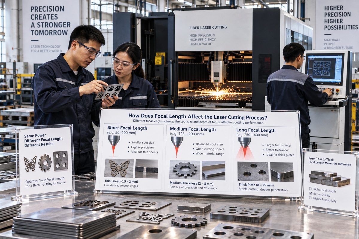
How Does Focal Length Affect the Laser Cutting Process?
Focal length is one of the most important optical parameters influencing the laser cutting process. It describes the distance between the focusing lens and the point where the laser beam converges to its smallest diameter. By determining the focused spot size, beam divergence, depth of focus, and power density delivered to the workpiece, focal length directly affects cutting speed, penetration capability, kerf width, edge quality, and overall process stability.
A short focal length generally produces a smaller focused spot and a higher power density. This concentrated energy can support fast cutting, narrow kerfs, and detailed contours, particularly when processing thin materials. However, the resulting depth of focus is relatively shallow, making the process more sensitive to variations in material flatness, nozzle height, and focal position. A longer focal length creates a larger spot with a greater depth of focus. Although its peak power density may be lower, the beam remains effective across a longer vertical range, which can improve performance when cutting thicker materials or workpieces with minor surface variations.
The influence of focal length cannot be evaluated independently. Laser power, beam quality, lens diameter, assist-gas type and pressure, nozzle design, cutting speed, material properties, and focal-point position all interact with the optical system. A focal length that performs well for thin stainless steel may not be ideal for thick carbon steel, aluminum, or nonmetallic materials. Likewise, selecting the wrong lens can result in incomplete penetration, excessive dross, wide kerfs, rough edges, overheating, or unstable cutting.
Understanding how focal length changes beam behavior allows operators and manufacturers to select suitable optics and optimize cutting parameters for specific applications. This article explains the relationship between focal length and laser cutting performance, examines the advantages and limitations of different focal lengths, and provides practical guidance for improving cut quality, productivity, and process reliability.
Table of Contents
Understanding Focal Length in Laser Cutting Systems
Focal length is a fundamental optical parameter in laser cutting systems because it helps determine how the laser beam is concentrated before it reaches the material. It influences the focused spot diameter, power density, beam convergence and divergence, depth of focus, and the usable distance between the optical components and the cutting zone. These factors subsequently affect cutting speed, kerf width, penetration, edge quality, and tolerance to changes in material height.
However, focal length is often confused with related terms such as focal point, focus position, working distance, and depth of focus. Although these concepts are connected, they describe different characteristics of the optical and cutting process. Understanding the distinction between them is essential when selecting a focusing lens, setting up a cutting head, or optimizing parameters for different materials and thicknesses.
Definition of Focal Length
Focal length is the optical distance over which a focusing lens causes an incoming collimated laser beam to converge toward its smallest beam diameter. In simplified terms, it is commonly described as the distance from the lens to the focal point. More precisely, it is measured from the optical principal plane of the lens or lens system rather than necessarily from the physical surface of the lens.
Laser cutting lenses are available in different focal lengths to support different processing requirements. A shorter focal length generally creates a smaller focused spot, a steeper convergence angle, and a higher power density. These characteristics can support narrow kerfs, detailed contours, and high cutting speeds in thin materials. However, the beam also diverges more rapidly after passing through the focus, resulting in a relatively short depth of focus.
A longer focal length generally produces a larger focused spot and a more gradual beam convergence angle. The maximum power density may be lower, but the beam diameter changes more slowly along the optical axis. This creates a greater depth of focus and can improve process tolerance when cutting thicker materials or workpieces with minor height variations.
The nominal focal length is primarily a property of the focusing optic. Nevertheless, actual beam behavior also depends on the laser wavelength, beam quality, input beam diameter, lens design, optical alignment, contamination, and thermal conditions.
How the Focusing Lens Shapes the Laser Beam
The beam leaving the laser source and beam-delivery system is normally too large and insufficiently concentrated for efficient cutting. The focusing lens redirects the beam toward the optical axis so that it converges into a small waist near the workpiece. At this beam waist, the laser energy is distributed across the smallest practical area, producing the high power density required to melt, vaporize, or chemically react with the material.
Before reaching the focus, the beam diameter gradually decreases and its power density increases. At the focal region, the beam reaches its minimum diameter and maximum power density. After passing through this region, the beam begins to diverge, causing the spot diameter to increase and the power density to decrease.
A shorter-focal-length lens bends the beam more strongly. This usually produces a smaller spot and higher power density, but the beam converges and diverges at steeper angles. A longer-focal-length lens shapes the beam more gradually, creating a longer and less sharply concentrated focal region.
The focused beam is not a perfect geometric point. Diffraction and the real beam quality of the laser prevent the spot from becoming infinitely small. The achievable spot size is influenced by the wavelength, beam quality factor, focal length, and beam diameter entering the lens. For a given wavelength and input beam size, reducing the focal length generally reduces the focused spot diameter. However, real cutting performance also depends on the ability of the optical system to maintain alignment, cleanliness, and thermal stability.
Focal Length Versus Focal Point
Focal length and focal point are closely related, but they are not interchangeable. Focal length is a distance and an optical property of the lens or complete focusing system. The focal point is the location where the focused beam reaches its minimum diameter and typically its highest power density.
For example, a cutting head may use a lens with a nominal focal length of 150 mm. The 150 mm value describes the optical focusing distance, while the focal point refers to the specific location created by that lens within or near the workpiece. Replacing the lens with one that has a different focal length changes the beam geometry and generally changes where the optical focus forms unless the cutting head is repositioned or adjusted.
In practical laser processing, the term “focal point” usually refers to a small focal region rather than a dimensionless point. The beam maintains a sufficiently small diameter across a limited axial distance surrounding the beam waist. The size of this region is important because laser cutting occurs through material with measurable thickness rather than on an infinitely thin surface.
The focal point may also shift because of optical contamination, temperature changes, lens deformation, incorrect installation, or changes in the collimated beam. Therefore, the nominal lens focal length alone does not guarantee that the actual focal point will remain correctly positioned during production.
Focal Length Versus Focus Position
Focal length describes how the optical system focuses the beam, whereas focus position describes where the focal point is located relative to the workpiece. Focus position is commonly expressed as being on the material surface, above the surface, or below the surface. It may also be specified as a positive or negative offset, although the sign convention can vary between machine manufacturers.
Changing the focus position does not necessarily change the focal length. A machine can move the cutting head, worktable, focusing lens, or internal focusing mechanism to reposition the focal point while continuing to use the same lens. Modern autofocus cutting heads can make this adjustment automatically according to the material type, thickness, and cutting process.
Positioning the focus near the top surface can provide high power density at the point where the beam enters the material. Moving it below the surface can distribute useful beam intensity deeper into the cut and may improve penetration or kerf behavior in certain thick-material applications. In some oxygen-assisted carbon-steel cutting processes, the focus may be placed above the material to create the beam and kerf conditions required by the process. The correct position depends on the material, thickness, laser type, assist gas, nozzle configuration, and desired cut quality.
Focal length determines the general shape and axial extent of the focused beam, while focus position determines which part of that beam interacts with each level of the material. Both must be selected correctly. A suitable focal length with an incorrect focus position can still cause incomplete cutting, excessive dross, wide kerfs, rough edges, or unstable penetration.
Focal Length Versus Working Distance
Working distance refers to the usable physical distance between a defined part of the cutting head and the workpiece or focal plane. Its exact meaning can vary among optical and machine manufacturers. It may refer to the distance from the last optical surface to the focal plane, from the protective window or lens housing to the workpiece, or from the nozzle tip to the material surface. For this reason, technical specifications should identify the reference points used for the measurement.
Focal length is an optical property, whereas working distance is a mechanical and operational measurement. They may be related, but they are rarely identical. The physical thickness of the lens, the location of its principal planes, protective windows, internal spacing, nozzle length, and cutting-head design all affect the actual working distance.
A longer focal length can make it possible to create a greater physical separation between the focusing optic and the processing zone. This can help protect sensitive optics from heat, smoke, spatter, and debris. It may also provide additional clearance for certain cutting applications. However, the final nozzle-to-workpiece standoff is normally much smaller and is controlled independently because assist-gas flow requires the nozzle to remain close to the material.
When changing to a lens with a different focal length, operators must confirm that the cutting head has enough adjustment range to position the focus correctly. They should also verify nozzle compatibility, collision clearance, capacitive height-control performance, and beam centering. A lens cannot be selected solely by comparing its focal length with the desired nozzle standoff.
Focal Length Versus Depth of Focus
Depth of focus is the axial range around the focal point within which the laser beam remains sufficiently concentrated for the intended cutting process. It describes how far the beam can travel along the optical axis before its diameter or power density changes beyond an acceptable limit.
A short-focal-length lens generally provides a small spot and high peak power density, but it also produces a short depth of focus. This makes the process more sensitive to material warping, surface-height variations, inaccurate focus settings, and changes in cutting-head position. Even a relatively small displacement may move the material outside the most effective part of the focused beam.
A longer-focal-length lens generally creates a larger spot with a longer depth of focus. The beam remains closer to its minimum diameter over a greater axial range, which can provide more consistent energy delivery through thick material or across an uneven surface. The tradeoff is that the larger spot usually reduces peak power density and may increase kerf width.
Depth of focus is not a single universal distance because its value depends on the acceptance criterion. One manufacturer may define it according to a permitted increase in spot diameter, while another may use a power-density or process-quality threshold. It is also affected by laser wavelength, beam quality, input beam diameter, lens condition, and optical alignment.
In production, the required depth of focus should match the material thickness, part geometry, surface condition, and height-control accuracy. Thin, flat sheets and detailed contours may benefit from a tightly focused beam, while thick or uneven workpieces may require a longer usable focal region.
Focal length determines how the focusing optics transform the incoming laser beam and strongly influences spot size, power density, convergence angle, beam divergence, and depth of focus. It should not be confused with the focal point, which is the location of the smallest beam waist; the focus position, which defines that location relative to the workpiece; the working distance, which describes a physical clearance within the cutting setup; or the depth of focus, which represents the usable axial range around the focus.
Shorter focal lengths generally provide smaller spots and higher power density, making them suitable for thin materials, narrow kerfs, and detailed cutting. Longer focal lengths generally provide a greater depth of focus and improved tolerance to material thickness or height variations, although they usually create a larger spot with lower peak power density.
Effective laser cutting therefore depends on selecting a focal length that matches the application and then accurately controlling the focus position, working distance, nozzle standoff, and other process parameters. Understanding these distinctions helps operators avoid setup errors, select suitable optics, and achieve more consistent cutting speed, penetration, kerf geometry, and edge quality.
Optical Principles Behind Focal Length
The influence of focal length on laser cutting begins with the way the focusing lens transforms a relatively broad, nearly collimated laser beam into a concentrated beam waist. This transformation determines the beam’s convergence angle, minimum spot diameter, power density, divergence rate, and usable focal range. Together, these characteristics influence how efficiently the laser energy enters the material and remains effective throughout the cutting depth.
Focal length does not determine cutting performance by itself. The incoming beam diameter, laser wavelength, beam quality, lens aperture, optical alignment, and condition of the protective components also affect the final beam geometry. Understanding these optical principles explains why a shorter focal length usually produces a smaller and more intense spot, while a longer focal length generally creates a larger spot with a more extended focal region.
Beam Convergence and Divergence
Before entering the focusing lens, the laser beam is usually collimated so that its diameter remains relatively stable as it travels through the cutting head. The focusing lens redirects the beam toward the optical axis, causing it to converge. Its diameter gradually decreases until it reaches the beam waist, after which it begins to diverge.
A short-focal-length lens bends the beam more strongly and creates a steeper convergence angle. The beam reaches its minimum diameter over a shorter distance and expands rapidly after passing through the focus. This geometry can produce high power density, but it also makes the process more sensitive to changes in focal position and material height.
A long-focal-length lens shapes the beam more gradually. The convergence and divergence angles are smaller, so the beam diameter changes less rapidly around the focus. This creates a longer usable focal region and can improve tolerance to workpiece-height variations. However, the resulting spot is usually larger and provides lower peak power density under otherwise identical conditions.
Beam convergence and divergence also affect the shape of the kerf. A rapidly converging and diverging beam may create greater differences between the kerf width at the top and bottom of the material. A more gradual beam profile can help maintain a more consistent kerf through thicker sections, although the final result also depends on focus position, assist gas, cutting speed, and material properties.
Beam Waist and Focused Spot Size
The beam waist is the location where the focused laser beam reaches its minimum cross-sectional diameter. In laser cutting, this minimum diameter is commonly referred to as the focused spot size. The power density is normally highest in this region because the laser energy is concentrated over the smallest area.
The beam waist is not an infinitely small point. Diffraction prevents light from being focused into a zero-diameter area, and real laser beams contain imperfections that further limit how tightly they can be focused. The minimum achievable spot therefore depends on focal length, wavelength, incoming beam diameter, and beam quality.
Spot size can be measured or reported according to different conventions. Some specifications define it according to a particular intensity level within the beam, while others use an encircled-energy diameter or an estimated geometric spot. These definitions may produce different numerical results, so the measurement method should be confirmed when comparing lenses or cutting heads.
A smaller beam waist can produce a narrow kerf, detailed contours, and high cutting speed in thin materials. However, it is accompanied by rapid beam expansion away from the focal plane. A larger waist distributes the energy over a wider area, reducing maximum intensity but increasing the axial range over which the beam remains close to its minimum size.
Actual spot size may be larger than the theoretical value because of lens aberrations, beam misalignment, contamination, thermal distortion, aperture clipping, or poor beam quality. Maintaining a clean and correctly aligned optical system is therefore essential for obtaining the expected benefit from a selected focal length.
Relationship Between Focal Length and Spot Diameter
When laser wavelength, beam quality, and incoming beam diameter remain unchanged, the focused spot diameter generally increases with focal length. A shorter focal length produces a smaller spot, while a longer focal length produces a larger spot.
The incoming beam diameter is also important. A broader beam filling more of the usable lens aperture can normally be focused into a smaller spot than a narrow beam passing through the same lens. However, the beam should not overfill the clear aperture because excessive clipping can distort the beam profile, increase diffraction effects, and cause unwanted heating.
Laser beam quality further modifies the relationship. A high-quality beam can be concentrated more tightly than a lower-quality beam with the same power, wavelength, beam diameter, and focal length. Consequently, two laser cutting systems using lenses with identical focal lengths may produce different spot sizes.
The proportional relationship between focal length and spot diameter applies only when the other optical conditions remain comparable. Replacing a lens may also change the beam path, clear aperture, working distance, aberrations, or internal configuration of the cutting head. Focal length should therefore be evaluated as part of the complete optical system rather than as an isolated specification.
Relationship Between Spot Size and Power Density
Power density describes how much laser power is delivered over a given area. As the focused spot becomes smaller, the same amount of power is concentrated into a smaller region, causing the power density to rise substantially. If the spot diameter is reduced by half while laser power remains unchanged, the beam area becomes approximately one-quarter as large, and the average power density becomes approximately four times greater.
This relationship explains why short-focal-length lenses can support fast cutting, narrow kerfs, and detailed features in thin materials. The high power density allows the workpiece to reach its melting or vaporization temperature rapidly.
A larger spot distributes the laser power over a wider area and produces lower power density. Although this may reduce the ability to cut fine features, it can create a broader processing zone and a more suitable kerf for removing molten material from thick sections. A larger spot can also reduce sensitivity to small positioning errors or variations in the workpiece surface.
The intensity within a laser spot is not perfectly uniform. In a Gaussian beam, intensity is greatest at the center and decreases toward the outer edge. As a result, peak intensity is higher than the average intensity across the spot. Other beam profiles distribute energy differently and may produce different cutting behavior even when their nominal spot diameters are similar.
The optical power reaching the focal region is not necessarily the same as the power absorbed by the material. Absorption depends on wavelength, surface condition, temperature, reflectivity, and angle of incidence. Energy can also be lost through lenses and protective windows. Higher optical power density therefore does not always produce a proportional increase in cutting efficiency.
Excessive power density can also create problems. It may cause vigorous vaporization, excessive spatter, unstable molten-material flow, or an enlarged heat-affected zone. The spot size and power density should be matched to the material, thickness, cutting speed, and assist-gas conditions.
Rayleigh Length and Depth of Focus
Rayleigh length describes how far the laser beam travels from the beam waist before its radius increases by a defined amount. It provides a useful indication of how quickly the beam expands away from its minimum diameter. The region extending on both sides of the waist is often used as an optical estimate of the depth of focus.
A small beam waist generally has a short Rayleigh length. It provides high intensity at the focal point, but the beam expands rapidly above and below that location. Cutting performance can therefore change significantly if the focus position shifts or the material surface varies in height.
A larger beam waist normally creates a longer Rayleigh length. The beam diameter changes more gradually, allowing useful power density to be maintained across a greater axial distance. This can benefit thick-material cutting and applications involving slightly uneven or distorted sheets.
For comparable input-beam conditions, increasing focal length usually increases depth of focus substantially. The resulting optical system becomes less sensitive to small errors in focus setting. However, the improvement comes with a larger spot and lower peak power density.
The practical depth of focus in laser cutting is not necessarily identical to its theoretical optical definition. Machine manufacturers may define it according to an acceptable change in spot size, power density, kerf width, or cutting quality. Material behavior, assist-gas flow, and process settings also determine how much of the optical focal range is genuinely useful.
Beam Quality and the M² Factor
The M² factor indicates how closely a real laser beam approaches the behavior of an ideal fundamental Gaussian beam. An ideal Gaussian beam has the lowest possible M² value. Real industrial lasers have higher values because of higher-order beam modes, thermal effects, source characteristics, and imperfections in the beam-delivery system.
A beam with a lower M² value can normally be focused into a smaller spot than a beam with a higher M² value when wavelength, focal length, and incoming beam diameter remain the same. It can therefore deliver greater brightness and power density to the workpiece.
A higher M² value indicates poorer focusability. The resulting spot is larger, and the beam diverges more strongly for a given waist size. Although a larger spot produced by a lower-quality beam may appear to create a longer focal region in some configurations, it does not provide the same brightness or cutting capability as a well-focused high-quality beam.
Beam quality is particularly important when producing fine features, using long beam-delivery paths, or operating at high laser power. Changes in beam quality can alter spot size and cutting behavior even when rated power and focal length remain unchanged.
Focal length should therefore be selected with consideration of the actual beam quality or beam parameter product of the laser source. A lens cannot completely compensate for poor beam quality, and a focal length that performs well with one laser source may not produce the same results with another.
Laser Wavelength and Focusing Performance
Laser wavelength affects diffraction and the minimum spot size that an optical system can theoretically produce. Under comparable optical conditions, a shorter wavelength can generally be focused into a smaller spot than a longer wavelength.
Fiber lasers used for metal cutting commonly operate at a wavelength close to one micrometer, while CO2 lasers operate at a wavelength of approximately ten micrometers. The shorter wavelength of the fiber laser contributes to its ability to achieve a small focused spot. However, actual performance also depends on beam quality, incoming beam diameter, focusing optics, and cutting-head design.
Wavelength also influences how effectively different materials absorb laser energy. A smaller spot does not automatically guarantee faster or better cutting if the material reflects a large portion of the incident energy. Absorption can change as the surface heats and melts, making the interaction dynamic throughout the cutting process.
Different wavelengths require different optical materials and coatings. A lens or protective window must transmit the operating wavelength efficiently and withstand the associated laser power. An incompatible, contaminated, or damaged optical component may absorb energy, overheat, shift the focus, or fail.
Wavelength, focal length, and beam quality should therefore be evaluated together. These factors determine the achievable spot size and beam brightness, while the material’s absorption characteristics determine how effectively that optical energy is converted into cutting action.
Useful Optical Relationships
Several general optical relationships are useful when evaluating focal length without relying on detailed calculations. A shorter focal length or larger incoming beam diameter produces a greater numerical aperture, which allows the beam to be focused more tightly. A longer focal length or smaller incoming beam diameter produces a lower numerical aperture, a larger spot, and a longer focal region.
The f-number provides another way to describe the relationship between focal length and the beam or aperture diameter. A lower f-number indicates stronger focusing and generally produces a smaller spot with a shorter depth of focus. A higher f-number indicates weaker focusing and generally creates a larger spot with a longer depth of focus.
Focused spot diameter increases with focal length, wavelength, and beam-quality factor when the other variables remain unchanged. It decreases as the beam diameter entering the focusing lens increases. These relationships explain why focal length alone cannot accurately predict the final spot size.
Power density changes inversely with the beam area. Reducing spot diameter therefore produces a much larger increase in intensity than the change in diameter might initially suggest. This makes spot-size control especially important in high-power laser cutting.
A small beam waist is also associated with greater divergence after the focus. Consequently, achieving both an extremely small spot and a very long depth of focus is difficult within a conventional focusing system. Laser cutting optics must balance these competing requirements.
These relationships describe general trends rather than exact production results. Lens aberration, beam truncation, astigmatism, thermal lensing, optical contamination, protective-window distortion, and non-Gaussian beam profiles can all cause actual performance to differ from theoretical expectations. Final optical selection should therefore be supported by manufacturer specifications, beam measurements, and cutting tests.
Focal length affects laser cutting by controlling how the beam converges toward its waist and diverges after passing through it. A shorter focal length generally produces a steeper convergence angle, smaller focused spot, and higher power density. A longer focal length creates a larger spot, more gradual divergence, and a longer usable focal region.
Spot size and power density are closely connected. Concentrating the same laser power into a smaller spot greatly increases intensity, which can improve thin-sheet cutting speed and fine-detail capability. A larger spot reduces peak intensity but may provide a more stable energy distribution through thick material.
Rayleigh length and depth of focus describe how rapidly the beam changes around the waist. A tightly focused spot provides high intensity but limited axial tolerance, while a larger waist remains effective over a greater distance. Beam quality and wavelength further influence the minimum achievable spot size and the beam’s divergence behavior.
These principles demonstrate why focal length cannot be selected independently. Effective optical design requires balancing focal length, wavelength, beam diameter, beam quality, power density, and depth of focus. The best configuration is the one that supplies sufficient cutting intensity while maintaining suitable beam geometry throughout the material thickness and under real production conditions.
Short, Medium, and Long Focal Lengths
Focusing lenses used in laser cutting are commonly described as having short, medium, or long focal lengths. These categories provide a convenient way to compare how strongly different optical systems focus the laser beam. In general, a short focal length produces a small, highly concentrated spot with a limited depth of focus, while a long focal length produces a larger spot with a more extended focal region. A medium focal length offers a balance between these characteristics.
These categories should not be treated as fixed numerical standards. The practical behavior of a focal length depends on the laser wavelength, incoming beam diameter, beam quality, cutting-head design, material, thickness, and required cut quality. Understanding the characteristics of each category helps manufacturers choose an optical configuration that provides an appropriate balance among power density, cutting precision, process tolerance, and material-thickness capability.
Characteristics of a Short Focal Length
A short-focal-length lens bends the incoming laser beam through a relatively steep convergence angle. Under otherwise identical conditions, this produces a smaller focused spot and higher power density than a longer-focal-length lens. The concentrated energy can rapidly heat, melt, or vaporize the material, making short focal lengths particularly effective for thin-sheet cutting, fine contours, narrow slots, and small features.
The smaller spot generally creates a narrower kerf and can improve geometric detail. It may also support high cutting speeds when processing thin materials because sufficient energy is delivered to a small area. These characteristics can be valuable when minimizing material waste or producing closely spaced parts.
The primary limitation is the relatively short depth of focus. The beam diameter increases rapidly above and below the focal point, so cutting performance becomes more sensitive to focal-position errors. Warped sheets, inconsistent material thickness, incorrect nozzle height, or unstable height control can move the cutting zone outside the most effective focal region.
A short focal length also produces a rapidly diverging beam after the waist. This can make it difficult to maintain a suitable beam diameter and power distribution through thick material. The narrow entrance kerf may restrict assist-gas flow or the removal of molten material, particularly when the beam must travel through a deep cut channel.
The shorter optical geometry may also reduce the available distance between the focusing optic and the processing zone, depending on the cutting-head design. This can increase the exposure of protective components to smoke, spatter, and heat. Therefore, clean optics, accurate beam alignment, flat material, and responsive height control become especially important.
Short focal lengths are not automatically the best choice whenever maximum intensity is desired. If the resulting spot is too small, the process may become unstable, overly sensitive, or unsuitable for the required kerf geometry. Excessive power density can also intensify vaporization, spatter, and local overheating.
Characteristics of a Medium Focal Length
A medium focal length provides a compromise between the small spot of a short focal length and the extended focal region of a long focal length. It normally produces moderate power density, a manageable kerf width, and sufficient depth of focus for a broad range of general cutting applications.
This balanced behavior makes medium focal lengths common in production environments that process multiple materials or thicknesses. They can provide adequate precision for thin and medium-thickness sheets while maintaining greater tolerance to focus variation than a very short focal length. The beam can remain suitably concentrated through a useful portion of the material thickness without requiring exceptionally precise surface conditions.
A medium focal length may also simplify process development. Operators can often achieve stable results across a wider parameter range because small variations in material flatness, nozzle height, or focus setting have less effect than they would with a more aggressive short-focus configuration. At the same time, the focused spot remains small enough to support reasonable cutting speed and edge definition.
However, a medium focal length is a compromise rather than a universal optimum. It may not provide the extremely narrow kerf or high power density required for delicate features in very thin material. It may also lack the depth of focus or clearance preferred for demanding thick-plate cutting. Production involving a narrow range of highly specialized parts may benefit from a shorter or longer focal length optimized specifically for that application.
For facilities that frequently change materials and thicknesses, a medium focal length can offer valuable versatility. It reduces the need to change optics continually and can provide a practical starting point for parameter development. Final suitability must still be verified through cutting trials because laser power, beam quality, assist gas, nozzle selection, and material properties strongly affect the outcome.
Characteristics of a Long Focal Length
A long-focal-length lens bends the beam more gradually, producing a shallower convergence angle and a larger focused spot. Although the resulting peak power density is generally lower, the beam diameter changes more slowly around the focal point. This creates a longer depth of focus and greater tolerance to variations in focal position.
The extended focal region can be beneficial for cutting thick materials because useful beam intensity can be maintained across a greater portion of the cut depth. The wider beam may also create a kerf that supports more effective assist-gas flow and easier removal of molten material. These characteristics can improve process stability in applications where maintaining a consistent cut channel is more important than producing the narrowest possible kerf.
A long focal length is generally less sensitive to minor changes in sheet height, material thickness, and focus position. It can therefore provide more consistent performance when processing large sheets, slightly uneven surfaces, or parts where maintaining perfect flatness is difficult. The greater physical working distance available in some cutting-head configurations may also help separate sensitive optical components from heat, smoke, and spatter.
The main disadvantage is the larger spot and lower power density. More laser power or a lower cutting speed may be required to achieve the necessary material interaction. Fine features, sharp internal corners, and narrow gaps may be more difficult to produce. The wider kerf can also increase material loss and influence dimensional compensation.
A longer focal length does not guarantee better thick-material cutting. If the spot becomes too large, the available power density may be insufficient for reliable penetration or efficient cutting. Its effectiveness depends on having adequate laser power, appropriate assist-gas delivery, suitable beam quality, and correctly optimized focus position.
Why “Short” and “Long” Are Relative Terms
There is no universal focal-length value at which a lens becomes short, medium, or long. These descriptions are relative to the optical system, laser source, and intended application. A focal length considered long in one cutting head may be treated as standard or medium in another.
Laser wavelength is one reason these classifications vary. A shorter-wavelength laser can generally produce a smaller focused spot than a longer-wavelength laser when the other optical conditions are comparable. Fiber laser and CO2 laser cutting systems may therefore obtain different spot sizes and depths of focus from lenses with similar nominal focal lengths.
The incoming beam diameter is equally important. A large beam entering the focusing lens can produce a smaller focused spot than a narrow beam using the same focal length. Beam quality, represented by the (M^2) factor or beam parameter product, also affects how tightly the beam can be focused. Comparing focal lengths without considering these factors can lead to misleading conclusions.
Cutting-head construction further influences the classification. The effective optical behavior may depend on both collimating and focusing lenses, internal lens spacing, beam-expansion settings, and zoom or autofocus mechanisms. In a variable-focus cutting head, the beam geometry may be adjusted without physically replacing the focusing lens.
Application requirements also change the meaning of short and long. A lens may be considered short for thick-plate cutting but medium for high-resolution thin-sheet processing. Manufacturers should therefore compare the resulting spot diameter, depth of focus, numerical aperture, working distance, and supported application range instead of relying only on a focal-length value expressed in millimeters or inches.
Main Selection Trade-Off
The main trade-off in focal-length selection is between tight energy concentration and an extended, tolerant focal region. A shorter focal length generally provides a smaller spot, higher power density, narrower kerf, and better capability for fine features. In exchange, it delivers a shorter depth of focus and greater sensitivity to focal-position errors, sheet distortion, and height variation.
A longer focal length generally provides a larger spot, longer depth of focus, more gradual beam divergence, and improved process tolerance. These characteristics can support stable cutting through thicker materials and across less uniform surfaces. The trade-off is lower peak power density, a potentially wider kerf, and reduced capability for fine details.
A medium focal length balances these competing effects and can be appropriate for general-purpose production. However, the best selection is not necessarily the lens that produces the smallest spot or the greatest depth of focus. It is the focal length that maintains sufficient power density and suitable beam geometry throughout the required cutting depth while delivering the desired speed, kerf width, edge quality, and process stability.
Selection should consider laser power, wavelength, beam quality, material type, thickness range, part geometry, assist gas, nozzle configuration, surface flatness, and height-control accuracy. Cutting trials remain essential because theoretical optical advantages do not always translate directly into better production results.
Short, medium, and long focal lengths create different balances of spot size, power density, beam divergence, depth of focus, and working clearance. Short focal lengths generally produce small, intense spots that support narrow kerfs, detailed features, and fast thin-sheet cutting, but they require accurate focus control and consistent material height.
Medium focal lengths provide balanced power density and focal tolerance, making them suitable for a broad range of general cutting tasks. Long focal lengths create larger spots and longer focal regions, which can improve tolerance to height changes and support stable processing through thicker materials, although they may reduce cutting intensity and fine-detail capability.
The terms “short,” “medium,” and “long” are relative rather than standardized. Their practical meaning depends on wavelength, beam diameter, beam quality, cutting-head design, and application requirements. For this reason, focal length should not be evaluated as an isolated specification.
The correct choice balances power concentration against usable focal depth. Manufacturers should select a focal length based on the complete cutting process and confirm its performance through application-specific testing. A properly matched optical configuration will provide sufficient intensity for efficient cutting while maintaining the beam geometry and tolerance required for consistent production.
How Focal Length Affects Laser Cutting Results
Focal length influences laser cutting results by changing the geometry and intensity distribution of the focused beam. It affects the minimum spot size, power density, convergence and divergence angles, and depth of focus. These optical changes influence how the laser heats the material, how the molten material moves through the kerf, and how effectively the assist gas removes it from the cutting zone.
A shorter focal length generally creates a smaller, more intense spot with a limited depth of focus. A longer focal length usually creates a larger spot with lower peak intensity but a longer usable focal region. Neither option is universally better. The correct choice depends on laser power, beam quality, material type, thickness, assist gas, nozzle configuration, focus position, and required cut quality.
Effect on Focused Spot Size
Under comparable optical conditions, a shorter focal length produces a smaller focused spot, while a longer focal length produces a larger spot. This relationship directly affects the size of the area receiving laser energy.
A small spot is useful for narrow contours, closely spaced parts, small holes, and detailed features. It can create a narrow kerf and reduce material loss. However, the beam diameter changes rapidly above and below the focal point, making the process more sensitive to focus errors and surface-height variations.
A larger spot covers a wider processing area and generally produces a wider kerf. Although it provides less geometric resolution, it can create a longer usable focal region and a more gradual change in beam diameter through the material thickness.
The actual spot size also depends on laser wavelength, beam quality, incoming beam diameter, lens condition, and optical alignment. For this reason, two machines using lenses with the same focal length may not produce identical spots or cutting results.
Effect on Power and Energy Density
When the same laser power is concentrated into a smaller spot, power density increases significantly. A short focal length can therefore create the high intensity needed to heat, melt, or vaporize material rapidly. In pulsed processing, a smaller spot also increases the amount of pulse energy delivered per unit area.
Higher power density can improve cutting speed and support fine-feature production, especially in thin materials. It can also help initiate piercing and establish the cutting front more quickly. However, excessive intensity may cause violent vaporization, unstable molten-material movement, increased spatter, or local overheating.
A longer focal length distributes the laser power over a larger spot, reducing peak power and energy density. This may require a slower cutting speed or greater laser power, but the broader energy distribution can support a wider and more stable cut channel in some thick-material applications.
The goal is not always to achieve the highest possible power density. The required intensity must be matched to the material’s absorption, melting behavior, thickness, and assist-gas process. Stable material removal is usually more important than maximum optical intensity alone.
Effect on Cutting Speed
A short focal length can increase cutting speed in thin materials because its small spot delivers high power density to the cutting front. The material reaches its melting or vaporization temperature quickly, allowing the machine to move at a higher feed rate while maintaining complete separation.
The advantage becomes less straightforward as material thickness increases. A short-focal-length beam diverges rapidly away from the focus, so its intensity may decrease substantially before reaching the bottom of a thick workpiece. A narrow kerf can also restrict assist-gas flow and make it more difficult to remove molten material.
A longer focal length may produce lower peak intensity, but its greater depth of focus can maintain a more consistent beam size through the material thickness. This can support stable cutting in thick plate, even if the maximum feed rate is lower than that achieved in thin material with a short focal length.
Cutting speed must be evaluated together with cut quality and process reliability. A theoretically fast optical configuration provides little benefit if it causes frequent incomplete cuts, excessive dross, or repeated parameter adjustments. The best focal length supports the highest sustainable production speed that meets the required quality standard.
Effect on Penetration Capability
Penetration capability depends on whether sufficient energy reaches the cutting front throughout the complete material thickness. A short focal length provides high intensity near the focal point, which can produce rapid initial penetration. However, the limited depth of focus means that the beam expands quickly away from the waist.
If a thick workpiece extends far beyond the effective focal region, the power density at the lower part of the cut may become insufficient. This can lead to partial penetration, intermittent cutting, heavy bottom-edge dross, or complete loss of the cut.
A longer focal length creates a larger spot but maintains a more consistent beam diameter over a greater axial distance. When adequate laser power is available, this extended focal region can improve energy delivery through thick material and support more reliable penetration.
Focus position remains critical. The focal point must be located so that the useful portion of the beam is distributed appropriately through the material. A suitable focal length with an incorrect focus position can still produce poor penetration. Material absorption, assist-gas pressure, nozzle size, and cutting speed also affect the result.
Effect on Kerf Width
Kerf width is influenced by the focused spot size, energy distribution, material response, focus position, and assist-gas action. A short focal length generally produces a smaller spot and can create a narrower kerf, particularly in thin material.
A narrow kerf improves dimensional efficiency and allows parts to be nested more closely. It may also reduce the amount of material that must be melted. However, if the kerf becomes too narrow, molten material and assist gas may have difficulty moving through the cut channel. This can increase dross or cause the cut to close behind the beam.
A long focal length usually creates a larger spot and a wider kerf. The wider channel may increase material loss, but it can also improve gas flow and molten-material evacuation in thick sections. This is one reason the smallest possible spot does not always produce the best overall result.
Kerf width is not necessarily constant through the material. Because the beam converges before the focus and diverges afterward, the upper, middle, and lower portions of the kerf may have different widths. Correctly matching focal length and focus position helps control these differences.
Effect on Kerf Taper and Wall Squareness
Kerf taper occurs when the cut is wider on one side of the material thickness than the other. Wall squareness describes how closely the cut surfaces approach a perpendicular relationship with the sheet surface.
A short focal length creates a steeply converging and diverging beam. If the material thickness extends significantly beyond the available depth of focus, the beam diameter can vary substantially from the top to the bottom of the cut. This may increase kerf taper and reduce wall squareness.
A longer focal length produces a more gradual change in beam diameter around the focus. This can help maintain a more consistent kerf width through thick material and improve wall parallelism. However, the larger spot may reduce fine-feature accuracy or produce an unnecessarily wide cut in thin material.
Focus position strongly influences the direction and degree of taper. Placing the focal point near the upper surface, within the material, or below the material changes where the narrowest part of the beam interacts with the cut. The optimal position depends on material type, thickness, assist gas, and the desired edge geometry.
Optical alignment is also important. A beam that is not centered in the nozzle or is not perpendicular to the workpiece can produce unequal wall angles even when focal length and focus position are correctly selected.
Effect on Edge Roughness and Striation Patterns
Laser-cut edges commonly display vertical or slightly curved lines known as striations. These patterns form as the cutting front moves and molten material flows downward through the kerf. Their spacing, direction, and depth provide useful information about process stability.
Focal length affects striation patterns by changing the beam diameter, energy distribution, and kerf geometry. A short focal length can produce smooth edges in thin material when the focus and speed are correctly set. Its high power density supports rapid melting and can create closely spaced, regular striations.
If the depth of focus is too short for the material, the beam may lose intensity toward the bottom of the cut. This can produce coarse lower-edge striations, irregular drag lines, or an uneven surface. Excessive intensity near the top may also enlarge the upper melting zone while the bottom remains insufficiently processed.
A longer focal length can distribute useful intensity over a greater depth and may improve edge consistency in thick material. However, if power density is too low or cutting speed is too high, the cutting front can become unstable and generate rough, pronounced striations.
Edge roughness is also affected by assist-gas flow, material composition, surface condition, nozzle alignment, vibration, and speed. Focal length should therefore be optimized as part of the complete process rather than treated as the sole cause of roughness.
Effect on Dross Formation
Dross forms when molten or partially solidified material remains attached to the bottom edge of the workpiece. Focal length can contribute to dross by affecting the energy available at the lower cutting front and the geometry of the kerf through which molten material must escape.
A short focal length may create a kerf that is narrow at the top but expands rapidly away from the focal region. If intensity becomes insufficient near the bottom, the material may not remain fully molten long enough to be expelled. A very narrow cut channel can also restrict assist-gas flow.
A longer focal length can improve energy consistency and create a wider channel for melt removal. This may reduce dross in thick-material cutting. However, if the spot is too large and power density is inadequate, the material may melt slowly, allowing viscous molten metal to accumulate at the lower edge.
Both excessive and insufficient energy can cause dross. Excessive heat may produce a large volume of molten material that the assist gas cannot remove effectively, while insufficient heat can leave partially melted deposits. The selected focal length must work with the correct focus position, speed, gas pressure, nozzle diameter, and stand-off distance.
Effect on the Heat-Affected Zone
The heat-affected zone is the region next to the cut edge where the material’s microstructure or properties change because of thermal exposure. Focal length influences this zone by controlling the area and intensity of laser heating.
A short focal length concentrates energy into a small area. When paired with an appropriately high cutting speed, it can minimize the total heat transferred into the surrounding material and produce a narrow heat-affected zone. This is often advantageous when cutting thin sheet or heat-sensitive components.
However, high local intensity can cause excessive melting or vaporization if the speed, power, or focus position is incorrect. Heat accumulation can become particularly noticeable at corners, during piercing, or when the machine decelerates.
A longer focal length distributes energy over a larger area. Its lower power density may require slower movement or longer interaction time, potentially increasing total heat input and widening the heat-affected zone. On the other hand, a stable process with efficient melt ejection may produce less thermal damage than an unstable short-focus process that repeatedly overheats the workpiece.
The final heat-affected zone depends on material thermal conductivity, thickness, cutting speed, assist gas, laser mode, and path strategy in addition to focal length.
Effect on Corner and Small-Feature Quality
A short focal length generally provides the small spot required for sharp corners, narrow slots, small holes, and detailed contours. The narrow kerf can preserve dimensional accuracy and allow the machine to reproduce fine geometry more effectively.
The high power density must be controlled carefully when the cutting head slows down at corners or small-radius curves. If laser power is not reduced with speed, excess energy can enlarge the kerf, round the corner, burn the edge, or create localized dross.
A longer focal length produces a larger spot that may limit the smallest achievable feature size. Internal corners may become more rounded, and narrow gaps may merge or become wider than intended. Dimensional compensation in the cutting software can correct some effects but cannot overcome the fundamental resolution limit imposed by the spot size.
Small-feature quality also depends on machine acceleration, motion-control accuracy, power modulation, lead-in design, and gas delivery. A short focal length provides optical capability for fine details, but the complete machine must control the process precisely enough to use that capability.
Effect on Piercing
Piercing creates the initial opening through which profile cutting begins. A short focal length can accelerate piercing because its high power density heats and removes material rapidly. It is particularly effective for piercing thin sheets and producing small entry points.
In thick material, a short depth of focus may limit the ability to maintain useful intensity as the hole becomes deeper. The narrow opening may also restrict the escape of molten material and vapor. This can increase spatter, extend piercing time, or contaminate the nozzle and protective window.
A longer focal length provides a more extended focal region and may support stable energy delivery as the pierce develops through thick material. Its larger spot can also create more space for vapor and molten material to escape. However, the lower peak intensity may increase the time required to begin the pierce.
Excessive power density during piercing can cause violent ejection, large craters, surface damage, or spatter on the cutting head. Modern systems may use staged piercing, pulsed power, changing gas pressure, or dynamic focus adjustment to control the process. The best focal length for profile cutting may therefore require modified piercing parameters.
Effect on Process Stability
Process stability describes the ability to maintain consistent cutting results despite normal variations in material, machine condition, and production environment. Focal length affects stability by determining how sensitive the beam is to changes in focal position and workpiece height.
A short focal length has a limited depth of focus, so small variations in sheet flatness, nozzle height, or lens position can cause noticeable changes in spot size and power density. It requires accurate capacitive height control, reliable autofocus, clean optics, and consistent material.
A longer focal length offers a greater depth of focus and can tolerate moderate height variations more effectively. This often creates a wider processing window for thick sheets or slightly uneven workpieces. However, if its larger spot reduces power density too far, the process may operate close to the penetration limit and become unstable for a different reason.
Thermal effects can also shift the actual focal position during extended operation. Contaminated lenses or protective windows absorb energy, heat up, and may change the beam path. The more focus-sensitive the optical configuration, the more strongly these changes can affect cutting performance.
Stable production requires a focal length that provides sufficient intensity without making the process unnecessarily sensitive. Focus calibration, lens inspection, nozzle centering, gas control, and parameter monitoring remain necessary regardless of the selected focal length.
Focal length influences nearly every visible and measurable laser cutting result. By changing spot size, power density, beam convergence, divergence, and depth of focus, it affects cutting speed, penetration, kerf geometry, edge roughness, dross, heat input, piercing, and process stability.
A short focal length generally provides a small spot and high power density. These characteristics support fast thin-sheet cutting, narrow kerfs, and detailed features, but they also create a limited depth of focus and greater sensitivity to focal-position errors.
A longer focal length produces a larger spot with lower peak intensity but maintains useful beam geometry across a greater axial range. This can improve penetration consistency, wall squareness, melt removal, and stability in thick-material cutting. The trade-off may include a wider kerf, slower speed, and reduced fine-feature resolution.
The best focal length is not simply the shortest or longest available. It is the one that delivers sufficient intensity throughout the required cutting depth while creating an appropriate kerf for assist-gas flow and molten-material removal. Final selection should be coordinated with focus position, laser power, beam quality, material thickness, nozzle configuration, assist gas, and cutting speed, then confirmed through application-specific cutting tests.
Focal Length and Focus Position: Two Different Variables
Focal length and focus position both affect how a laser beam interacts with the workpiece, but they describe different aspects of the optical system. Focal length is a characteristic of the focusing lens or complete optical assembly. It helps determine the minimum spot size, convergence angle, divergence angle, and depth of focus. Focus position describes where the smallest part of that focused beam is located relative to the material surface.
Changing the focal length modifies the shape of the focused beam. Changing the focus position moves that beam geometry upward or downward relative to the workpiece. A cutting system may therefore use the same lens while adjusting the focus above, at, or below the material surface. For reliable processing, the lens focal length and the focus position must be selected and optimized together.
Why These Terms Are Frequently Confused
Focal length and focus position are frequently confused because both contain the word “focus” and both influence spot size at the workpiece. Machine interfaces, operating manuals, and sales literature may also use terms such as focal point, focal distance, focus height, focus offset, and working distance without clearly defining them.
Focal length normally remains fixed as long as the same focusing lens and optical configuration are used. For example, moving the cutting head closer to the sheet changes the location of the focal point relative to the material, but it does not change the optical focal length of the lens.
Focus position is an adjustable process parameter. It may be changed by moving the focusing lens, adjusting an internal collimating or focusing mechanism, moving the complete cutting head, or changing the relative position of the workpiece. Autofocus cutting heads can perform this adjustment automatically without requiring the operator to replace the lens.
The confusion is increased by the fact that changing focal length can also move the focal point unless the cutting head is mechanically readjusted. Replacing a short-focal-length lens with a longer one changes both the beam geometry and the physical location at which the beam naturally converges. The operator must then reposition the focus relative to the material.
It is helpful to think of focal length as defining the shape of the focused beam and focus position as defining where that shape is placed. A short-focal-length lens creates a small waist with a short focal region, while a long-focal-length lens creates a larger waist with a longer focal region. The selected beam waist can then be positioned above, on, or below the material surface.
Focus Above the Material Surface
When the focus is above the material surface, the beam reaches its minimum diameter before it arrives at the workpiece. By the time it contacts the upper surface, it has already begun to diverge. The spot at the surface is therefore larger than the minimum spot at the focal point, and it generally becomes wider as it travels deeper into the material.
This arrangement can create a relatively wide upper kerf and distribute energy over a broader area. In some oxygen-assisted carbon-steel cutting processes, an above-surface focus can help establish suitable kerf geometry and support the exothermic reaction between oxygen and the heated metal. The wider cut channel may also assist the flow of oxygen into the cutting zone and the removal of molten oxides.
An above-surface focus can be useful when an extremely small spot would create excessive local intensity or an overly narrow kerf. It may provide more stable heat distribution for certain materials and thicknesses. However, because the beam continues to expand inside the workpiece, power density at the lower cutting front may become too low if the focus is positioned excessively high.
Possible symptoms of an excessively high focus include incomplete penetration, a wide upper kerf, a narrow or poorly formed lower cut, heavy bottom dross, and coarse lower-edge striations. The useful adjustment range depends on focal length because a short-focal-length beam diverges more rapidly than a long-focal-length beam.
Focus above the material should not be considered a universal rule for a particular gas or material. The optimum setting depends on the laser source, cutting head, plate thickness, beam quality, nozzle, and parameter strategy.
Focus at the Material Surface
When the focus is positioned at the material surface, the beam reaches its minimum diameter and maximum power density close to the point where it enters the workpiece. This provides rapid heating and can produce a narrow upper kerf.
Surface focus is often suitable for thin materials because the beam does not need to remain tightly concentrated over a long distance. The high intensity at the entry point can support fast cutting, precise contours, small features, and rapid piercing. It can also provide a convenient reference condition during process setup and focus calibration.
After entering the material, the beam begins to diverge. In a thin sheet, this expansion may be small enough that useful power density remains available through the entire thickness. In a thick plate, however, the spot may become considerably larger before reaching the bottom surface, especially when a short focal length is used.
If the focal region is too short for the material thickness, a surface focus can produce a narrow and clean upper edge but a rough or incomplete lower edge. Bottom dross, kerf taper, and irregular striations may increase because the energy distribution is concentrated too strongly near the top.
A surface focus is therefore not automatically the neutral or best setting. It is one possible position whose suitability depends on the relationship between material thickness and the usable depth of focus.
Focus Below the Material Surface
When the focus is below the upper surface, the beam is still converging as it enters the material. Its diameter decreases as it travels toward the focal point and then increases after passing through it. Positioning the waist inside the workpiece can distribute useful intensity deeper into the cut.
A below-surface focus is frequently used when processing thicker materials or when high energy density is required within the lower portion of the cutting front. It is common in many high-pressure nitrogen-cutting processes for stainless steel and aluminum, although the optimum position varies with equipment and application.
Moving the focus into the material can improve penetration, reduce lower-edge dross, and produce more consistent striations through the thickness. It may also help balance the kerf width between the upper and lower surfaces by placing the most concentrated part of the beam closer to the middle or lower region of the cut.
If the focus is placed too far below the surface, the spot at the top of the material becomes too large, and the entry power density decreases. This can slow piercing, widen the upper kerf, increase top-edge rounding, or prevent the cutting front from forming correctly. The beam may also begin diverging too strongly before it reaches the bottom if the selected position does not match the material thickness and focal depth.
The best below-surface position is not necessarily the geometric center of the material. It must account for absorption, changing kerf geometry, molten-material flow, and assist-gas behavior. The setting should be established through verified process data or controlled cutting tests.
Positive and Negative Focus Conventions
Positive and negative focus values are used to describe the position of the focal point relative to a reference surface. Unfortunately, the sign convention is not standardized across all laser manufacturers, controllers, and cutting-head suppliers.
In one common convention, a positive focus value places the focal point above the material surface, while a negative value places it below the surface. In another system, the signs may be reversed because the controller defines the direction according to lens movement, machine-axis direction, or the coordinate system used by the cutting head.
A displayed value of zero may indicate that the focus is located at the top surface, but it may also represent a calibrated mechanical reference within the cutting head. If the machine has not been calibrated correctly, the displayed value may not correspond to the actual optical focus.
Operators should never assume that a positive or negative number has the same meaning on every machine. The equipment manual should specify whether the value refers to the focal point relative to the sheet, the direction of internal lens movement, or another reference position.
When transferring cutting parameters between machines, it is safer to record the physical focus location as above, at, or below the material surface in addition to the controller value. Lens type, nozzle configuration, material thickness, and calibration method should also be documented. A parameter copied from another system may produce a different physical focus position even if the numerical value appears identical.
Focus calibration should be checked after lens replacement, protective-window replacement, cutting-head service, collision, or any event that could change the optical path. Common verification methods include focus-ramp tests, angled-plate tests, or manufacturer-specified calibration procedures.
Why Lens Selection and Focus Adjustment Must Be Optimized Together
Lens selection establishes the fundamental beam geometry, including the minimum spot size, convergence and divergence rates, and depth of focus. Focus adjustment determines where that geometry interacts with the workpiece. Optimizing only one variable cannot guarantee good cutting results.
A short-focal-length lens may provide the high power density required for fine features, but its limited depth of focus leaves little tolerance for an incorrect focus setting. Even a small positional error can change the spot size at the surface or reduce the intensity available at the bottom of the cut.
A long-focal-length lens provides a greater usable focal range and can tolerate larger focus variations. However, its larger minimum spot may not deliver enough power density for thin-material speed or small-feature resolution. Moving the focus cannot make that lens produce the same minimum spot as a properly designed shorter-focal-length system.
The optimum focus position also changes with lens selection. A focus offset that performs well with one focal length may produce excessive taper, dross, or incomplete penetration with another because the beam expands at a different rate. Whenever the focal length changes, the focus position, cutting speed, laser power, gas pressure, nozzle size, and piercing parameters should be reviewed.
Material requirements must also be considered. Thin sheets and detailed contours may benefit from a short focal length with the focus near the surface. Thick materials may require a longer focal length and a focus position that distributes useful intensity deeper into the kerf. Oxygen, nitrogen, and air cutting can require different focus strategies because they remove material through different combinations of heating, oxidation, pressure, and molten-metal flow.
Modern autofocus systems make focus adjustment faster, but they do not eliminate the need for correct lens selection. Autofocus can reposition the available beam waist; it cannot fundamentally change the spot size and depth of focus created by the optical system unless the head includes additional variable-beam or zoom optics.
Focal length and focus position are related but distinct variables. Focal length determines the general geometry of the focused beam, including its minimum spot size, convergence, divergence, and depth of focus. Focus position determines where that beam waist is located relative to the material.
Placing the focus above the surface allows a diverging beam to enter the workpiece and may support certain oxygen-assisted cutting processes. Positioning it at the surface provides maximum intensity near the entry point and can be effective for thin materials and fine features. Positioning it below the surface distributes concentrated energy deeper into the cut and can improve thick-material penetration and lower-edge quality.
Positive and negative focus values cannot be interpreted reliably without checking the machine manufacturer’s convention. The same sign may describe opposite physical directions on different systems, and a displayed zero value may depend on machine calibration.
Successful laser cutting requires focal length and focus position to be optimized together. Lens selection establishes the beam’s capabilities, while focus adjustment places those capabilities where they are most useful within the material. Coordinating both variables with laser power, cutting speed, assist gas, nozzle configuration, and material thickness is essential for achieving stable penetration, controlled kerf geometry, low dross, and consistent edge quality.
Focal Length for Different Material Thicknesses and Geometries
The most suitable focal length for laser cutting depends on both material thickness and part geometry. Thin sheets and fine features usually benefit from a small focused spot and high power density, while thick materials often require a longer usable focal region and a kerf wide enough for effective assist-gas flow and molten-material removal. Complex geometries introduce additional considerations, including changes in cutting angle, surface height, stand-off distance, and effective material thickness.
These guidelines should not be treated as fixed rules. The meaning of a short, medium, or long focal length varies with laser wavelength, beam diameter, beam quality, cutting-head design, and application. Focal length must also be coordinated with focus position, laser power, cutting speed, assist gas, nozzle selection, and motion-control capability.
Thin-Sheet Cutting
Thin-sheet cutting generally benefits from a short or medium focal length that produces a small focused spot and high power density. Because the beam only needs to remain effective through a limited material thickness, a long depth of focus is usually less important than speed, narrow kerf width, and fine-feature capability.
A small spot can heat the material rapidly and support high feed rates. It can also produce narrow cuts, sharp corners, and closely spaced contours. These characteristics are especially useful when maximizing material utilization or producing parts with small gaps and detailed geometry.
However, a very short focal length can make the process sensitive to sheet distortion, focus errors, and changes in nozzle height. Thin sheets may warp from residual stress, thermal input, or inadequate support. If the material moves outside the limited focal region, kerf width and edge quality may become inconsistent.
High power density can also create excessive heating when the cutting head decelerates at corners or around small features. Power modulation and speed control are therefore important. In high-power machines, a medium focal length or a slightly adjusted focus position may provide better stability than the shortest available lens.
For thin materials, the preferred focal length should provide enough intensity for high-speed cutting without making the process unnecessarily sensitive or creating excessive local melting.
Medium-Thickness Cutting
Medium-thickness materials usually require a balance between power density and depth of focus. A medium focal length is often suitable because it can maintain adequate intensity while providing a sufficiently extended focal region.
The beam must deliver enough energy to establish and maintain the cutting front through the complete thickness. At the same time, the kerf must allow assist gas and molten material to move downward without excessive resistance. A spot that is too small may create a narrow channel that restricts melt removal, while a spot that is too large may lower the power density and reduce cutting speed.
A medium focal length can offer a practical compromise. It is generally less sensitive to surface-height variations than a short focal length but still provides sufficient concentration for controlled kerf formation and reasonable feature resolution.
The optimum focus position may be at the surface or within the material, depending on the material type and cutting gas. Stainless steel, aluminum, and carbon steel may require different energy distributions because they absorb laser energy and remove molten material in different ways.
Medium-thickness cutting often represents the widest operating range for a general-purpose cutting system. A versatile optical configuration can be valuable when production includes multiple materials, thicknesses, and part geometries. However, the parameters should still be optimized for each combination rather than relying on one universal setting.
Thick-Plate Cutting
Thick-plate cutting places greater demands on depth of focus, penetration, kerf geometry, and molten-material removal. A medium-to-long focal length is often preferred because it produces a more gradual change in beam diameter through the material.
The longer focal region helps maintain useful energy deeper in the cut. It can also create a wider kerf that improves assist-gas flow and provides more space for molten metal, vapor, and oxidation products to escape. These characteristics can reduce bottom-edge dross and improve cutting stability.
A short focal length may produce very high intensity near the focal point, but the beam can expand too rapidly outside this limited region. The upper section may cut efficiently while the lower cutting front receives insufficient energy. This can lead to incomplete penetration, pronounced kerf taper, rough lower-edge striations, or heavy dross.
A long focal length is not automatically the best choice for every thick plate. If the spot becomes too large, the power density may be insufficient to sustain the cutting front. The machine may then require lower speed, higher power, or different gas conditions. An excessively wide kerf can also increase material loss and reduce dimensional accuracy.
The preferred focal length must provide enough intensity throughout the material while supporting stable gas flow and melt ejection. Thick-plate cutting is particularly dependent on correct focus position, nozzle centering, gas purity, pressure, plate quality, and surface condition.
Cutting Small Holes and Narrow Slots
Small holes and narrow slots require a focused spot that is significantly smaller than the intended feature. A short focal length is often advantageous because it can create a narrow kerf and provide the high power density required for detailed cutting.
A small spot improves the ability to reproduce tight radii, narrow gaps, and small circular features. It can also reduce the amount of material removed, helping the finished feature remain closer to its programmed dimensions.
Feature quality depends on more than focal length. The cutting head must change direction rapidly, particularly when producing small holes. Limited acceleration, servo following error, or poor path control can distort the feature even when the optical spot is sufficiently small.
Heat accumulation is another concern. The beam repeatedly passes close to previously heated material, and cutting speed is often limited by the small path radius. Excessive power density can enlarge the hole, round corners, burn narrow bridges, or leave dross. Dynamic power control, suitable lead-in placement, and carefully selected gas conditions are essential.
For small features in thick material, the requirement for a small spot may conflict with the need for a long depth of focus. A short focal length can provide good resolution but may not maintain adequate energy through the thickness. In such cases, a medium focal length, optimized focus position, or alternative hole-making process may produce better results.
The achievable hole diameter and slot width depend on material thickness, laser type, machine accuracy, and quality requirements. Focal length alone cannot overcome an unfavorable ratio between feature size and material thickness.
Cutting Large Contours
Large contours generally place less emphasis on minimum spot size because the feature dimensions are much greater than the kerf width. Process stability, edge consistency, straightness, and tolerance to material-height variation may be more important than maximum optical resolution.
A medium focal length is often suitable for large contours because it provides a balance between cutting intensity and focus tolerance. A longer focal length may be beneficial when processing thick sheets, large plates with minor flatness variations, or parts requiring extended uninterrupted cuts.
During long cutting paths, thermal distortion can cause the sheet or part to move. A focal length with a greater depth of focus can help maintain a more consistent spot size as the surface height changes. Reliable capacitive height control remains necessary, but a less sensitive optical configuration can widen the process window.
A short focal length can still be effective for large contours in thin material, especially when high speed and narrow kerf width are priorities. The large physical size of the contour does not automatically require a long focal length. Material thickness, flatness, edge-quality requirements, and available laser power remain the main considerations.
Large contours may also involve long acceleration and deceleration zones, lead-ins, and thermal expansion. The selected focal length should support stable cutting across the complete path without requiring frequent parameter corrections.
Bevel Cutting
Bevel cutting positions the laser beam at an angle to the material surface to create sloped edges for welding preparation, assembly, or finished-part geometry. The beam travels through a greater effective material thickness than it would in a perpendicular cut, making depth of focus and energy distribution particularly important.
A medium or long focal length can provide the extended focal region needed to maintain effective intensity along the angled cutting front. It may also provide additional clearance between the cutting head and workpiece, reducing collision risk as the head tilts.
A short focal length can produce a narrow and precise bevel in thin material, but its limited depth of focus may become problematic as the bevel angle or material thickness increases. The beam may be tightly focused near one part of the cut while becoming too large elsewhere.
Beveling also changes the relationship between the nozzle, surface, kerf, and assist-gas flow. The gas jet may not travel symmetrically through the angled kerf, and molten material may be more difficult to remove from one wall. A slightly wider kerf produced by a longer focal length can sometimes improve material ejection, but excessive spot size may reduce edge accuracy.
The focus must be calibrated relative to the tilted beam and actual material surface. Accurate tool-center-point control, nozzle alignment, collision avoidance, and angular compensation are essential. A focal length selected for vertical cutting may require different focus and process settings during bevel cutting.
Tube and Profile Cutting
Tube and profile cutting involves curved surfaces, changing incidence angles, varying wall orientations, and frequent transitions between different contours. Round tubes, square tubes, rectangular profiles, channels, and irregular extrusions each create different focusing challenges.
A short focal length can provide the small spot needed for slots, holes, tabs, and detailed joints in thin-walled tubes. However, the limited depth of focus makes the process sensitive to tube ovality, profile distortion, chuck runout, seam height, and inaccurate centering.
A medium focal length often provides a useful balance for general tube cutting. It can maintain sufficient power density while tolerating moderate variations in the distance between the cutting head and curved surface. For thicker-walled tubes or profiles with significant dimensional variation, a longer focal length may improve stability.
The cutting angle changes continuously around curved surfaces. As the beam moves away from perpendicular incidence, the effective path through the wall becomes longer, and the kerf geometry becomes asymmetrical. Focus position, cutting speed, and gas conditions may need to change according to feature location and surface orientation.
Internal walls create another challenge. After passing through the near wall, the beam or molten material may damage the opposite wall. Focal length, power, and focus position should be selected to complete the intended cut without delivering excessive energy into the tube interior.
Reliable tube cutting requires accurate rotary-axis synchronization, surface tracking, profile measurement, and support control. Focal length contributes to process tolerance but cannot compensate for poor workpiece positioning or excessive mechanical runout.
Three-Dimensional Cutting
Three-dimensional laser cutting is used for formed sheet-metal components, stamped parts, automotive body structures, hydroformed tubes, and other non-flat workpieces. The cutting head may move along several axes while continuously changing its angle and distance relative to the surface.
A medium or long focal length is often beneficial because it provides greater depth of focus and working clearance. These characteristics can help accommodate minor errors in part placement, surface shape, robot positioning, and height measurement. Additional clearance can also reduce the likelihood of nozzle collisions when the head tilts around complex features.
A short focal length may be selected when three-dimensional parts contain small holes, narrow slots, or detailed trimming paths. Its smaller spot improves feature resolution, but the machine must maintain highly accurate position and stand-off control. Fixture repeatability becomes especially important.
The effective material thickness changes when the beam strikes the surface at an angle. The focus position that works on a perpendicular section may not produce the same result on a steeply inclined surface. Advanced systems may use autofocus, surface sensing, or programmed focus offsets to adapt to these changes.
Three-dimensional cutting also requires accurate calibration of the beam center, nozzle axis, tool center point, and motion system. Robotic systems must account for path accuracy and joint movement, while gantry-based systems must coordinate several linear and rotary axes.
Focal length should be selected according to the required balance among detail resolution, positional tolerance, working clearance, and effective cutting depth. Dynamic focus adjustment can expand the process range, but it cannot fully compensate for unsuitable beam geometry or inaccurate part positioning.
Material thickness and part geometry determine which focal-length characteristics are most valuable. Thin sheets and small features generally benefit from a short focal length that produces a small spot, high power density, and narrow kerf. The limited depth of focus requires accurate height control and careful management of heat around corners and closely spaced contours.
Medium-thickness materials often require a balanced focal length that provides sufficient intensity, moderate depth of focus, and stable kerf formation. Thick plates usually benefit from a medium or long focal length that maintains useful beam geometry through a greater depth and supports effective gas flow and molten-material removal.
Large contours may favor process stability and tolerance to sheet distortion, while bevel cutting requires sufficient focal depth and working clearance along an angled cut. Tube, profile, and three-dimensional cutting introduce curved surfaces, changing incidence angles, variable stand-off distances, and collision risks. These applications often benefit from a more tolerant focal region, although short focal lengths may still be required for fine details.
No focal length is ideal for every combination of thickness and geometry. Final selection should consider laser power, wavelength, beam quality, material, focus position, assist gas, nozzle design, motion accuracy, and surface-tracking capability. Application-specific cutting tests remain the most reliable way to confirm that the chosen optical configuration delivers the required speed, accuracy, edge quality, and stability.
Focal Length in Different Laser Cutting Technologies
Focal length performs the same basic optical function in every laser cutting system: it helps determine how the beam converges, the size of the focused spot, the power or energy density at the workpiece, and the depth of focus. However, the practical effect of a particular focal length varies considerably among fiber, CO2, diode, and short-pulse laser systems.
Each technology has a different wavelength, beam profile, beam quality, delivery method, power range, and material-interaction mechanism. A focal length that produces a small, intense spot in one system may create a substantially larger or differently shaped spot in another. Lens selection must therefore be based on the complete beam-delivery system and application rather than the nominal focal-length value alone.
Fiber Laser Cutting
Fiber laser cutting systems commonly operate in the near-infrared region and deliver the laser beam to the cutting head through an optical fiber. Inside the cutting head, a collimating lens transforms the emerging beam into a nearly parallel beam, and a focusing lens concentrates it onto or within the workpiece.
The relatively short wavelength and generally good beam quality of industrial fiber lasers allow them to produce small focused spots and high power densities. A short focal length can further reduce the spot size, supporting fast thin-sheet cutting, narrow kerfs, small holes, and detailed contours. The trade-off is a limited depth of focus and greater sensitivity to material-height variation, focus calibration, and optical contamination.
A longer focal length produces a larger spot and a more extended focal region. This can be useful for thick materials because the beam diameter changes more gradually through the cutting depth. The wider kerf may also improve assist-gas flow and the removal of molten material. However, the laser must have sufficient power and beam brightness to maintain effective cutting intensity with the larger spot.
Modern fiber laser cutting heads often include autofocus capability. The operator or control system can move the focal point above, at, or below the surface without replacing the focusing lens. This adjustment changes the location of the beam waist but does not fundamentally change the focal length or minimum spot size created by the optical configuration.
Some cutting heads also use variable collimation or zoom optics to modify the beam diameter entering the focusing lens. This allows the system to alter spot size and depth of focus across a broader processing range. In these systems, cutting performance cannot be predicted from the focusing-lens focal length alone because the collimating optics and beam-expansion setting also influence the final beam geometry.
High-power fiber laser cutting systems place significant thermal demands on protective windows, focusing lenses, and other optical components. Even minor contamination can absorb energy, cause heating, and shift the actual focus. The selected focal length must therefore be combined with effective optical monitoring, cooling, and maintenance.
CO2 Laser Cutting
CO2 lasers typically operate at a much longer infrared wavelength than fiber lasers. The beam is normally delivered from the resonator to the cutting head through a series of mirrors rather than an optical fiber. A focusing lens near the cutting head then concentrates the beam onto the material.
Because the CO2 laser wavelength is longer, it generally produces a larger diffraction-limited spot than a shorter-wavelength laser under comparable optical conditions. CO2 laser cutting systems often compensate by using a large beam diameter, suitable beam-expansion optics, and carefully selected focusing lenses.
Short-focal-length lenses can provide a smaller spot and higher power density for cutting thin materials, producing fine details, or processing applications that require a narrow kerf. However, the shorter focal region makes focus control more sensitive, particularly when cutting warped sheets or materials with variable surface height.
Longer focal lengths provide a greater depth of focus and more working clearance. They may be preferred for thicker materials, applications with surface variations, or processes where the lens should remain farther from smoke and debris. The associated larger spot may reduce fine-feature resolution and require adjustments to laser power or cutting speed.
CO2 laser cutting includes a wide range of materials, such as plastics, wood, textiles, paper products, rubber, ceramics, and certain metals. The optimum focal length can vary substantially because these materials respond differently to thermal energy. Thin films and fabrics may benefit from a tightly focused spot, while thick acrylic, foam, wood, or other materials may require a longer focal region to maintain effective cutting through the depth.
Optical alignment is particularly important in mirror-delivered CO2 laser cutting systems. Misaligned mirrors can change the beam position and angle at the focusing lens, producing an off-center or distorted focal spot. Beam diameter may also vary across a large machine bed if the beam-delivery system is not properly designed or adjusted.
The focusing optics must be made from materials that transmit the CO2 laser wavelength. Contamination, coating damage, and thermal absorption can change focusing behavior or lead to lens failure. A nominal focal length will only produce the expected result when the beam-delivery path and lens condition are properly maintained.
Diode and Direct-Diode Laser Cutting
Diode lasers generate laser light directly from semiconductor emitters. In conventional fiber lasers, diode output pumps a separate gain medium before the final beam reaches the workpiece. In direct-diode systems, the combined diode output is shaped and delivered to the processing head without using a fiber-laser gain stage.
Direct-diode lasers can operate at different wavelengths depending on the semiconductor material and system design. Many industrial systems operate in the near-infrared region, while blue diode lasers are used for applications involving materials that absorb blue wavelengths efficiently, such as copper and certain other nonferrous metals.
The focusing behavior of a diode laser depends strongly on beam quality and beam shape. Individual diode emitters often produce asymmetric beams with different divergence characteristics in two directions. Industrial systems use optical correction, beam combining, and fiber coupling to create a more usable processing beam, but the final profile may differ from the near-Gaussian beam associated with some other laser sources.
A short focal length can increase power density, but it cannot completely compensate for a large beam parameter product or an uneven beam profile. If the incoming beam has limited focusability, reducing focal length may provide only a modest reduction in spot size while decreasing working distance and depth of focus.
A longer focal length can provide additional clearance and improve tolerance to height variation, but it also enlarges the spot and lowers power density. The best choice depends on whether the process prioritizes concentrated intensity, line width, working distance, or uniform energy distribution.
Some direct-diode systems intentionally use rectangular, elongated, or top-hat-like spots rather than attempting to produce the smallest possible circular spot. These beam profiles can be advantageous for selected cutting, welding, heat treatment, or surface-processing applications. In such cases, focal length affects both the spot dimensions and the intensity distribution, and a single spot-diameter value may not fully describe the result.
Material absorption at the diode wavelength is also important. A wavelength that is absorbed efficiently can produce effective cutting even if the focused spot is larger than that of another laser cutting system. Focal-length selection must therefore consider both optical focusability and the way the material responds to the wavelength.
Ultrafast and Short-Pulse Laser Cutting
Short-pulse laser cutting includes nanosecond, picosecond, and femtosecond systems. Picosecond and femtosecond lasers are generally described as ultrafast lasers. Instead of relying primarily on continuous melting and assist-gas ejection, these systems remove material through highly concentrated pulses that can produce ablation, vaporization, photochemical effects, or a combination of mechanisms.
Focal length determines the spot size and the amount of pulse energy delivered to each unit of area. A short focal length creates a small spot and high energy density, helping the pulse exceed the material’s ablation threshold. This is useful for micromachining small holes, fine slots, precision contours, thin films, semiconductor materials, glass, ceramics, and medical components.
The small spot created by short-focus optics also produces a limited depth of focus. The surface must remain accurately positioned relative to the beam waist. Even small changes in material thickness, surface height, or fixture accuracy can reduce ablation efficiency or change the feature dimensions.
A longer focal length provides greater working distance and a longer focal region but reduces the energy density delivered by each pulse. If the energy density falls below the effective removal threshold, cutting efficiency can decrease sharply. Increasing pulse energy may restore performance, but this can raise the risk of optical damage, plasma shielding, air breakdown, or unwanted thermal effects.
Many short-pulse systems use galvanometer scanners and field lenses to move the focused beam rapidly across the workpiece. In these systems, focal length affects not only spot size and depth of focus but also the available scanning field. A longer-focal-length field lens generally supports a larger working area, while a shorter-focal-length field lens provides a smaller spot over a more limited field.
Telecentric and specialized flat-field optics may be used to keep the beam angle and focus more consistent across the processing area. Even with these optics, spot size and energy distribution can vary near the edge of the field. Scanner calibration and lens correction data are therefore important for precision cutting.
Ultrafast processing can produce a very small heat-affected zone, but only when pulse energy, repetition rate, overlap, focal position, and scanning speed are properly controlled. A small spot with excessive pulse overlap can still accumulate heat and damage the surrounding material.
Why Identical Focal-Length Values Do Not Guarantee Identical Results
Two laser cutting systems can use lenses with the same nominal focal length and still produce very different spot sizes, depths of focus, power densities, and cutting results. Focal length describes only one property of the optical system.
Laser wavelength is a major source of variation. Shorter wavelengths can generally be focused into smaller spots than longer wavelengths under comparable conditions. A fiber laser and a CO2 laser using the same nominal focal length will therefore not automatically produce the same focal geometry.
Beam quality is equally important. A high-quality beam can be focused more tightly and deliver greater brightness than a lower-quality beam. Fiber core diameter, resonator mode, diode-beam combination, thermal effects, and delivery optics can all influence beam quality.
The beam diameter entering the focusing lens also changes the result. A larger incident beam can normally be focused more tightly than a smaller beam using the same focal length, provided the lens aperture is not overfilled. The collimating-lens focal length, beam expander, and internal optical spacing therefore affect the final spot.
Beam profile creates additional differences. A Gaussian, multimode, top-hat, rectangular, ring-shaped, or asymmetric beam distributes energy differently within the focused area. Two systems may report similar spot diameters while producing different peak intensities and material interactions.
Lens construction also matters. Nominal focal length is not necessarily identical to back focal length, working distance, or the physical distance between the lens and material. Lens thickness, curvature, refractive index, protective windows, and cutting-head design affect where the actual focus forms.
Optical aberrations, alignment errors, aperture clipping, contamination, coating condition, and thermal lensing can further change the real focal spot. At high power, absorbed heat may shift the focus during operation even though the nominal lens specification remains unchanged.
Finally, laser power, pulse characteristics, material absorption, assist gas, nozzle design, cutting speed, and focus position determine how the optical beam translates into cutting performance. A focal-length value should therefore never be used as the only basis for comparing machines or selecting process parameters.
Focal length influences spot size, intensity, depth of focus, and working clearance in every laser cutting technology, but its practical effect depends on the characteristics of the laser source and beam-delivery system.
Fiber lasers combine a short wavelength with generally good focusability, allowing them to produce small spots and high power densities. CO2 lasers operate at a longer wavelength and use mirror-based beam delivery, making beam diameter, alignment, and lens condition particularly important. Diode and direct-diode systems can have distinctive wavelengths, beam shapes, and beam-quality characteristics that affect how much benefit can be obtained from a shorter focal length. Ultrafast and short-pulse lasers depend on tightly controlled energy density and often use scanning optics that balance spot size against working area and depth of focus.
Identical focal-length values do not guarantee identical cutting results. Wavelength, beam quality, incident beam diameter, optical design, beam profile, lens material, thermal behavior, and focus position all influence the actual focused beam.
The appropriate focal length must be selected within the context of the complete laser cutting system and application. Manufacturer specifications, beam measurements, material-response data, and controlled cutting tests provide a more reliable basis for selection than nominal focal length alone.
Material-Specific Focal-Length Considerations
The effect of focal length varies with the optical, thermal, and physical properties of the material being cut. Absorption, reflectivity, thermal conductivity, melting temperature, viscosity, oxidation behavior, thickness, and surface condition all influence how the material responds to a focused laser beam.
A short focal length generally provides a smaller spot and higher power density, while a longer focal length provides a larger spot and greater depth of focus. However, material type alone does not determine the correct lens. Focal length must be coordinated with material thickness, laser wavelength, beam quality, assist gas, focus position, cutting speed, and required edge quality.
Carbon Steel
Carbon steel can be cut with oxygen, nitrogen, or compressed air. Oxygen-assisted cutting uses an exothermic reaction to contribute additional heat, while nitrogen and air cutting rely more heavily on energy supplied directly by the laser. The selected assist gas therefore affects the most suitable focal-length strategy.
Thin carbon steel generally benefits from a short or medium focal length. The resulting small spot and high power density support rapid heating, narrow kerfs, detailed contours, and high cutting speeds. When using oxygen, the focus may be positioned near or above the surface to establish an appropriate kerf and sustain the oxidation reaction, although the correct position depends on the machine and process.
Thick carbon steel often benefits from a medium or long focal length. The greater depth of focus helps maintain usable energy through the plate, while the wider kerf can improve oxygen flow and allow molten iron and oxides to escape. A very short focal length may deliver excessive intensity near the top but insufficient energy at the lower cutting front.
An excessively long focal length can produce a spot that is too large for the available laser power. This may slow the cut, produce rough striations, or cause incomplete penetration. Carbon-steel parameters must balance laser intensity with oxygen pressure, nozzle size, focus position, and controlled oxidation.
Stainless Steel
Stainless steel is commonly cut with high-pressure nitrogen when an oxide-free edge is required. Because nitrogen does not provide the same exothermic contribution as oxygen, the laser must supply most of the energy required to melt the material. The assist gas must then eject the molten metal from the kerf.
Thin stainless steel can be cut efficiently with a short or medium focal length. A small spot provides the high power density needed for fast cutting and can produce a narrow kerf with good dimensional accuracy. Careful power modulation is necessary around corners and small features to avoid local overheating.
As thickness increases, a medium or long focal length may provide better energy distribution and a more suitable kerf for gas flow. A focus position below the upper surface is often used to deliver concentrated energy deeper into the material, but the exact setting must be established for the machine and thickness.
Molten stainless steel can be relatively difficult to remove if the kerf is too narrow or gas delivery is inadequate. A slightly larger spot and wider cut channel may reduce bottom dross in thick sections. However, excessive spot size lowers power density and may require slower cutting.
Edge color, roughness, striations, and dross should be evaluated when optimizing the optical setup. Focal length must work together with nitrogen purity, pressure, nozzle centering, stand-off distance, and cutting speed.
Aluminum
Aluminum has high thermal conductivity and can rapidly carry heat away from the cutting zone. It is also reflective at several industrial laser wavelengths, particularly before the surface begins to heat. These characteristics create a need for sufficient power density and stable beam delivery.
Thin aluminum generally benefits from a short or medium focal length that provides a small spot and concentrated energy. This helps establish the cut quickly and limit the time available for heat to spread into the surrounding material. High-pressure nitrogen is commonly used when a clean, oxide-free edge is required.
Thicker aluminum may require a medium or longer focal length to maintain useful energy through the material and create enough kerf width for molten-metal removal. The focus is often positioned within the material, but the preferred setting varies with power, thickness, alloy, and cutting head.
Aluminum melt can adhere to the lower edge if power density, speed, or gas flow is insufficient. A focal length that is too short may create a narrow kerf that restricts ejection, while one that is too long may reduce intensity below the level required for stable penetration.
Different aluminum alloys can respond differently because of variations in thermal conductivity, reflectivity, and melting behavior. Cutting parameters developed for one alloy should not be assumed to work identically for another.
Copper and Brass
Copper and brass present significant challenges because they are highly thermally conductive and reflective at many laser wavelengths. A large portion of the incident energy may initially be reflected or conducted away from the cutting zone, making sufficient intensity and wavelength selection especially important.
For thin copper and brass, a short focal length can provide the concentrated power needed to initiate and sustain cutting. Fiber lasers are generally more suitable than CO2 lasers for many copper and brass applications because these materials absorb the shorter fiber-laser wavelength more effectively. Blue diode lasers can offer even stronger absorption in some copper-processing applications, although beam quality and system design remain important.
As thickness increases, a medium focal length may provide a better balance between intensity and usable focal depth. An extremely small spot can create rapid local heating, but the beam may not remain effective through the complete thickness. A slightly larger kerf can also improve the removal of molten metal.
Reflected energy can damage or destabilize a laser source that is not designed for reflective materials. Appropriate back-reflection protection, verified processing limits, correct piercing strategies, and clean optics are essential. Selecting a short focal length does not by itself make reflective-material cutting safe or reliable.
Brass contains zinc, which can generate hazardous fumes during cutting. Both copper and brass require effective extraction. Material composition and thickness should be verified before finalizing the optical and process parameters.
Coated and Galvanized Metals
Coated and galvanized metals contain surface layers whose absorption, vaporization temperature, and chemical behavior differ from the base metal. Examples include zinc-coated steel, painted sheet, protective films, plated metals, and prefinished products.
The focal length is generally selected primarily according to the base material and total thickness. Thin coated sheets may benefit from a short or medium focal length that penetrates the coating quickly and establishes the main cut with minimal delay.
However, concentrated energy can cause the coating to vaporize suddenly, generating spatter, smoke, or surface damage. A coating may also alter the piercing response and create inconsistent absorption across the sheet. If the process is too aggressive, the finish may blister, discolor, or peel near the cut.
For thicker coated materials, a medium or long focal length can provide the depth of focus needed for the substrate while maintaining a suitable kerf for removing molten metal and coating residue. Piercing parameters may need to differ from profile-cutting parameters to control coating ejection and protect the nozzle and cover glass.
Galvanized steel produces zinc-containing fumes and requires effective extraction. Protective films should only be laser cut when the film composition is known to be compatible with the process. Unknown coatings should be investigated before cutting because some can release toxic or corrosive gases.
Plastics and Acrylic
Plastics vary widely in their absorption, melting behavior, decomposition products, and compatibility with laser processing. CO2 lasers are commonly used because many organic polymers absorb the CO2 laser wavelength effectively. Fiber lasers are generally less suitable for cutting clear acrylic and many unfilled plastics unless additives or absorptive layers are present.
Thin acrylic and plastic sheets can often be cut with a short or medium focal length. A small spot supports narrow kerfs, detailed contours, and high cutting speeds. Acrylic can develop a smooth, polished-looking edge when power, speed, airflow, and focus are correctly balanced.
Thick acrylic usually benefits from a longer focal length because the beam must remain effective through a greater depth. The focus may be placed within the sheet to balance the upper and lower kerf widths. An excessively short focal length can create a narrow top section but excessive divergence deeper in the material, producing taper or incomplete cutting.
A spot that is too large or a speed that is too slow can create a wide heat-affected zone, excessive melting, bubbles, edge rounding, or discoloration. Different plastics may char, ignite, soften, or produce stringy melt rather than a clean edge, so test cuts are essential.
Material identification is critical. PVC and other chlorine-containing materials should not be laser cut because they can release toxic and corrosive gases. Other plastics may also emit hazardous fumes, making appropriate ventilation, filtration, and manufacturer-approved compatibility checks necessary.
Wood and Wood-Based Materials
Wood is a natural and nonuniform material. Density, moisture, grain direction, resin content, adhesives, and surface coatings can change across a single sheet. Plywood, medium-density fiberboard, oriented strand board, and laminated products behave differently from solid wood.
A short or medium focal length can provide the small spot and high intensity needed for detailed cutting in thin wood products. This supports narrow kerfs, intricate patterns, and relatively high speeds. However, very high local intensity can increase charring if the cutting speed or airflow is not properly controlled.
Thick wood and wood-based panels may benefit from a medium or long focal length that maintains useful intensity through the depth. The extended focal region can reduce taper and improve the consistency of the lower edge. Multiple passes may sometimes be used, but they can increase charring, smoke deposition, and kerf width.
A longer focal length alone cannot overcome poor material uniformity. Dense knots, glue layers, voids, or high-moisture areas may cut differently from surrounding material. Adhesive-filled products can produce more smoke and edge residue than solid wood.
Air assist helps control flame, remove smoke, and reduce residue on the lens and workpiece. Effective extraction and fire monitoring are essential because wood dust, resin, and cutting debris are combustible.
Textiles, Paper, and Thin Organic Materials
Textiles, paper, cardboard, leather, and other thin organic materials generally require limited cutting depth but benefit from a small spot and precise energy control. A short focal length can produce fine contours and narrow cuts without requiring excessive power.
Because these materials are thin, depth of focus is usually less critical than spot size, cutting speed, and thermal control. The focus is commonly positioned near the upper surface, although the optimum setting depends on the material and machine.
Synthetic textiles may melt and form a sealed edge, which can prevent fraying. Too much power density or a speed that is too slow can create a wide, hardened bead or cause the material to shrink. Natural fabrics and paper are more likely to char, discolor, or ignite.
A medium focal length may provide more tolerance when processing stacked layers, textured fabrics, corrugated cardboard, or materials that do not lie perfectly flat. However, cutting multiple layers can trap smoke, cause layers to fuse, or produce inconsistent edges.
Vacuum hold-down, clean support surfaces, accurate height control, and effective extraction are important. Flame detection and fire prevention are essential when cutting paper, fabric, leather, and other combustible materials.
Ceramics, Composites, and Specialty Materials
Ceramics, composites, glass-based materials, laminates, and specialty engineering materials require highly application-specific focal-length selection. Their behavior depends on brittleness, thermal conductivity, reinforcement type, resin content, layer structure, transparency, and absorption at the laser wavelength.
Ceramics can crack or develop thermal damage when subjected to steep temperature gradients. A short focal length creates the high intensity required for ablation or localized removal, particularly with pulsed or ultrafast lasers, but the small focal region demands accurate height control. A longer focal length may offer greater tolerance and working distance but can lower energy density below the effective removal threshold.
Fiber-reinforced composites are difficult because the reinforcement and matrix may absorb energy differently. Carbon fibers, glass fibers, thermoplastic matrices, and thermoset resins can respond at different rates. A small, intense spot can reduce the width of the processed region, but it may also overheat one component while failing to remove another efficiently.
For thick or uneven composite panels, a medium or long focal length can provide additional focal tolerance. However, longer interaction times may increase resin decomposition, delamination, fiber exposure, or heat-affected damage. Pulse duration and wavelength may be more important than focal length in some precision applications.
Layered and coated specialty materials can change behavior as the beam passes from one layer to another. The focal position and processing parameters may need to account for different absorption and thermal properties through the stack.
Some composites, ceramics, and specialty materials release hazardous dust, fibers, or decomposition products. Their exact composition should be confirmed before laser processing, and suitable extraction and filtration must be used. Application testing is essential because general focal-length recommendations may not predict the behavior of a specific formulation.
Material properties change the way focal length influences laser cutting. Carbon steel can benefit from oxidation-assisted cutting and may use a wider kerf in thick sections, while stainless steel and aluminum depend more heavily on laser energy and high-pressure gas to remove molten material. Copper and brass require careful control because of their reflectivity and thermal conductivity.
Coated and galvanized metals add surface layers that can alter piercing, absorption, and fume generation. Plastics and acrylic require consideration of wavelength compatibility, melting behavior, and decomposition products. Wood, paper, and textiles benefit from a small spot for detailed cutting but require careful heat, smoke, and fire control.
Ceramics, composites, and specialty materials may involve brittle fracture, delamination, uneven absorption, or ablation thresholds that make wavelength and pulse characteristics as important as focal length.
Across these materials, short focal lengths generally support fine features and high power density, while longer focal lengths provide greater depth of focus and tolerance for thick or uneven workpieces. Final selection must consider the complete combination of material, thickness, laser technology, beam quality, assist gas, focus position, and safety requirements. Controlled cutting tests remain essential for verifying speed, kerf geometry, edge quality, dross, and process stability.
Interaction Between Focal Length and Other Cutting Parameters
Focal length cannot be optimized independently of the other parameters in a laser cutting process. It establishes the beam’s basic geometry, including the focused spot size, convergence angle, divergence rate, and depth of focus. Laser power, cutting speed, assist gas, nozzle configuration, beam profile, operating mode, and material position determine how that optical geometry performs in practice.
When focal length changes, the effective power density, kerf geometry, and tolerance to focal-position variation also change. Parameters developed for one lens may therefore produce incomplete cuts, excessive dross, rough edges, or unstable piercing when applied to another. Reliable process development requires the optical and mechanical settings to be optimized as a coordinated system.
Laser Power
Laser power and focal length work together to determine the intensity delivered to the workpiece. A short focal length concentrates the available power into a smaller spot, producing high power density. A longer focal length distributes the same power over a larger spot, lowering peak intensity but increasing the usable focal range.
A lower-power laser may require a relatively small spot to achieve sufficient intensity for penetration. However, using an excessively short focal length can create a process that is highly sensitive to material height, focus calibration, and optical contamination.
High-power systems can use a larger spot while still maintaining enough intensity for effective cutting. A medium or long focal length may improve thick-plate performance by creating a longer focal region and a wider kerf for molten-material removal. It can also reduce excessive local vaporization near the upper surface.
More power does not automatically compensate for an unsuitable focal length. Increasing power when the spot is too large may increase heat input without producing the required energy distribution through the material. Likewise, combining high power with an excessively small spot can create spatter, unstable melt flow, optical contamination, and an enlarged heat-affected zone.
At high power levels, absorbed energy can heat the protective window and focusing optics, causing the actual focal position to shift during operation. Lens cleanliness, cooling, and focus monitoring become increasingly important.
Cutting Speed
Cutting speed determines how long the laser interacts with each area of material. Focal length determines how concentrated that energy is and how it is distributed through the cutting depth.
A short focal length can support high cutting speeds in thin material because its small spot provides high power density. If the speed is too low, the concentrated beam may deliver excessive heat, causing a wide kerf, top-edge rounding, burning, or dross.
A longer focal length usually produces lower peak intensity. Thin-material cutting may therefore require a lower speed unless sufficient laser power is available. In thick plate, however, the longer focal region may allow a more stable cutting front and reduce interruptions caused by loss of penetration.
If speed is too high for the selected focal length, the beam may not deliver enough energy to complete the cut. Common symptoms include intermittent penetration, trailing striations, rough lower edges, and heavy dross. If speed is too low, excess material may melt, the kerf may widen, and heat may spread into the surrounding workpiece.
Speed also changes during acceleration, deceleration, cornering, and small-feature cutting. A short-focus configuration can be especially sensitive to these changes because its high power density produces rapid heat accumulation. Dynamic power control is often required to maintain consistent edge quality.
Assist-Gas Type
Assist gas removes molten or vaporized material from the kerf, protects the processing area, and can influence the chemical reaction at the cutting front. Its interaction with focal length depends on whether the gas is reactive, inert, or a mixture.
Oxygen supports an exothermic reaction when cutting carbon steel. Because the oxidation process contributes additional heat, the optical system does not have to supply all the energy required for material removal. A focal length and focus position that create a suitable kerf for oxygen flow can be more important than achieving the smallest possible spot.
Nitrogen is generally used when an oxide-free edge is required. It does not provide significant additional heat, so the laser must melt the material while high-pressure gas ejects it. The focal length must provide sufficient power density and a kerf wide enough for effective gas flow and molten-metal removal.
Compressed air contains oxygen and nitrogen and can provide a combination of reactive and mechanical effects. Its optimum focal-length setting depends on material type, thickness, air quality, and available pressure.
For nonmetallic materials, air or inert gas may be used to remove smoke, cool the surface, limit flaming, or prevent contamination. A highly concentrated spot may cut quickly but can produce burning or melting if airflow and speed are not correctly matched.
Changing assist-gas type often requires changes in focus position, pressure, nozzle, speed, and power. The same focal length may remain usable, but the complete parameter set should be redeveloped.
Assist-Gas Pressure
Assist-gas pressure controls the force available to remove molten material from the kerf. Its effectiveness depends on nozzle geometry, stand-off distance, kerf width, gas type, and cutting-front stability.
A short focal length can produce a narrow kerf. While this reduces material removal, the narrow channel may restrict gas flow, especially in thick material. Increasing pressure may help, but excessive pressure can create turbulence, shock structures, and unstable molten-metal movement rather than improving the cut.
A medium or long focal length generally produces a wider kerf, providing more space for gas and molten material to move. This can be advantageous in thick stainless steel or aluminum cut with high-pressure nitrogen. However, an unnecessarily wide kerf increases gas consumption and may reduce dimensional accuracy.
Oxygen cutting normally uses a different pressure range and flow strategy from high-pressure nitrogen cutting. Excessive oxygen pressure can disturb the reaction or produce an overly wide kerf. The focal length should create beam and kerf conditions that support controlled oxidation rather than relying on pressure alone.
Gas pressure should be adjusted only after confirming that the beam is centered, the nozzle is undamaged, and the focus is correctly positioned. Pressure cannot reliably compensate for insufficient power density or an inappropriate focal length.
Nozzle Diameter and Nozzle Type
The nozzle forms and directs the assist-gas jet into the kerf. Its diameter and internal design must match the material, gas, pressure, stand-off distance, and kerf conditions created by the focused beam.
A small nozzle opening can create a concentrated gas jet and reduce gas consumption, but it leaves less tolerance for beam misalignment. The beam must pass through the center without contacting the nozzle. This is particularly important with a steeply converging beam or after changing the optical configuration.
A larger nozzle can deliver greater gas flow and may be useful for thick-material cutting. It can complement a medium or long focal length that produces a wider kerf. However, a nozzle that is too large may reduce gas-flow efficiency, increase consumption, or create unsuitable pressure distribution at the workpiece.
Different nozzle designs support different gas-flow patterns and cutting processes. Single-layer, double-layer, and specialized high-pressure nozzles may be used according to the gas and material. The preferred design for oxygen-assisted carbon-steel cutting may differ from the one used for high-pressure nitrogen cutting.
Nozzle diameter should not be selected solely according to focal length. The complete beam path, required gas flow, plate thickness, focus position, and cutting-head specifications must be considered. Beam centering should be checked whenever the lens, nozzle, or protective optics are serviced.
Nozzle Stand-Off Distance
Nozzle stand-off distance is the physical gap between the nozzle tip and the material surface. It should not be confused with focal length, working distance, or focus position, although changes in stand-off can affect the location of the focal point relative to the material if the optical system does not compensate.
A small and stable stand-off helps the gas jet enter the kerf before it spreads significantly. If the nozzle is positioned too far from the surface, the gas loses concentration and becomes more vulnerable to surrounding airflow. Molten-material removal may become less effective, increasing dross and roughness.
If the nozzle is too close, reflected heat, spatter, or molten material may damage it. The risk of collision also increases when cutting warped sheets or passing over previously cut parts.
A short focal length has limited depth of focus, making the process more sensitive to changes in stand-off and surface height. Even a small variation can move the workpiece away from the intended focal region. A longer focal length offers more tolerance, but consistent stand-off remains essential for gas delivery.
Capacitive height control is commonly used for conductive sheet metal, while other sensing methods may be required for nonconductive materials. The height-control system must respond quickly enough to follow the surface without introducing vibration or excessive nozzle movement.
Beam Mode and Beam Profile
Beam mode and beam profile describe how laser energy is distributed across the beam. A near-Gaussian beam concentrates most of its energy near the center, while multimode, top-hat, ring-shaped, rectangular, or other profiles distribute energy differently.
Focal length affects every profile, but it does not make them behave identically. A high-quality beam can generally be focused into a smaller spot than a multimode beam using the same focal length. The resulting power density and divergence will also differ.
A Gaussian-like beam with a short focal length can provide the concentrated center intensity needed for fine features and thin-sheet speed. A broader or ring-shaped profile may create a wider melt zone and support stable kerf formation in thick materials. Some modern laser cutting systems can change the beam profile to match different cutting tasks.
The spot may also be asymmetric, particularly in certain diode or poorly aligned optical systems. In this case, kerf width and edge quality can vary with cutting direction. Replacing the lens or changing focal length may alter the severity of the effect but will not correct the underlying beam-quality or alignment problem.
Focal-length selection should therefore consider the actual beam parameter product and intensity distribution rather than assuming that rated power alone describes the beam.
Continuous-Wave and Pulsed Operation
Continuous-wave operation delivers laser power continuously while the beam moves along the cutting path. It is widely used for fusion and reactive cutting because it supports a stable molten front. Focal length determines the steady spot size and intensity distribution acting on that front.
A short focal length can provide the high continuous power density needed for rapid thin-sheet cutting. A medium or long focal length may provide a more stable energy distribution through thick material, especially when combined with sufficient laser power.
Pulsed operation delivers energy in separate pulses. Even when average power is moderate, peak power can be very high. A short focal length can concentrate each pulse into a small area, supporting piercing, microcutting, or ablation.
Excessive pulse intensity can produce violent vaporization, plasma formation, spatter, cracking, or damage to the optics and workpiece. A longer focal length lowers energy density and increases depth of focus but may prevent the pulse from reaching the required removal threshold.
Pulse duration, pulse energy, repetition rate, overlap, and cutting speed all interact with spot size. Parameters developed for continuous-wave cutting cannot be transferred directly to pulsed cutting, even when focal length and average power appear similar.
Many industrial systems use pulsed or modulated output during piercing and continuous output during contour cutting. Each stage may require a different focus position, power setting, pressure, or timing strategy.
Material Flatness and Height Control
Material flatness determines whether the surface remains at a consistent distance from the cutting head. Focal length determines how tolerant the process is to variations in that distance.
A short focal length creates a small spot with a limited depth of focus. Warped sheets, raised edges, surface waviness, or poor support can move the cutting zone outside the optimum focal region. The result may be changing kerf width, intermittent penetration, rough edges, or increased dross.
A longer focal length creates a more extended focal region and can tolerate moderate height variation. This may improve consistency when cutting large sheets, thick plates, tubes, formed parts, or naturally uneven materials. However, a long focal length cannot compensate for severe distortion or inaccurate positioning.
An automatic height-control system maintains the nozzle stand-off while the machine moves. Autofocus adjusts the lens or internal optics to position the beam waist. These functions are related but different: height control manages the physical nozzle-to-surface gap, while autofocus manages the optical focus position.
Height-control performance can be affected by rapid contours, small parts, reflective surfaces, slag, coatings, electrical discontinuities, or transitions near sheet edges. Machine acceleration and sensor response must be fast enough to follow the surface without causing collisions or oscillation.
Consistent material support, sheet leveling, accurate calibration, and proper height sensing remain essential. Selecting a longer focal length may widen the operating window, but it should not replace correct mechanical preparation and control.
Focal length interacts with every major laser cutting parameter. Laser power determines whether the selected spot provides sufficient intensity, while cutting speed controls how much energy is delivered to each area. Assist-gas type and pressure influence chemical reactions, kerf flow, and molten-material removal.
Nozzle diameter, nozzle design, and stand-off distance determine how effectively the gas jet reaches the cutting front. Beam mode and profile affect the actual intensity distribution produced by a given lens. Continuous-wave and pulsed operation require different balances of spot size, peak intensity, and focal depth. Material flatness and height control determine whether the workpiece remains within the useful focal region.
A parameter change that improves one aspect of cutting may create a problem elsewhere. A smaller spot can increase speed but reduce focus tolerance. A wider kerf can improve melt ejection but consume more material and gas. Higher pressure may remove dross but also create turbulence if the nozzle and kerf are mismatched.
For this reason, changing focal length should be treated as a change to the complete process configuration. Power, speed, gas, nozzle, stand-off, focus position, and height-control settings should be reviewed and verified through controlled cutting tests. The best results come from balancing these parameters rather than optimizing any one of them independently.
How to Select the Right Focal Length
Selecting the right focal length requires more than deciding whether a short or long lens is preferable. Focal length affects spot size, power density, beam convergence, depth of focus, working clearance, kerf geometry, and sensitivity to changes in material height. The best choice must therefore match the complete production requirement rather than one isolated cutting condition.
A short focal length generally favors high power density, narrow kerfs, and fine features, while a longer focal length favors greater depth of focus, working clearance, and tolerance to height variation. A medium focal length often provides a practical balance for mixed production. Final selection should consider the materials, thicknesses, geometries, laser source, cutting head, quality targets, and productivity requirements of the application.
Define the Material Range
Begin by identifying every material the machine is expected to cut. Carbon steel, stainless steel, aluminum, copper, brass, acrylic, wood, composites, and coated materials interact differently with laser energy. Their absorption, reflectivity, thermal conductivity, melting behavior, and reaction with assist gas influence the most suitable optical configuration.
Material grade should also be considered. Different stainless-steel, aluminum, or copper alloys may not respond identically. Coatings, surface films, scale, oxidation, moisture, adhesives, and reinforcement fibers can further change absorption and cutting behavior.
If production is limited to one material, the focal length can be optimized specifically for its thermal and optical characteristics. A facility processing many materials may benefit from a more versatile medium focal length, interchangeable lens cartridges, or a variable-beam cutting head.
Laser compatibility must be confirmed before focal-length selection. A different lens cannot make an unsuitable material safe or practical to process. Unknown plastics, coatings, composites, and laminates should be identified because some may release toxic or corrosive emissions.
Determine the Thickness Range
Material thickness is one of the most important factors in selecting focal length. Thin sheets generally require a small spot and high power density rather than an extended focal region. A short or medium focal length can therefore support fast cutting, narrow kerfs, and detailed features.
Thick materials require the beam to remain effective through a greater axial distance. A medium or long focal length may provide better energy distribution, a more consistent kerf through the depth, and additional space for assist gas and molten material to move.
The most frequently processed thicknesses should receive more weight than the maximum advertised capacity. Selecting optics solely for an occasional maximum-thickness job may reduce efficiency and feature quality across the majority of daily production.
If the thickness range is exceptionally broad, a single fixed focal length may require significant compromises. Interchangeable lenses, autofocus, variable collimation, adjustable beam profiles, or separate cutting heads may provide better results. Autofocus can move the beam waist, but it cannot fully reproduce the spot size and depth of focus of a different optical design.
Establish Quality Requirements
Quality requirements should be defined before the lens is selected. Relevant criteria include kerf width, dimensional tolerance, edge roughness, wall squareness, striation pattern, dross level, heat-affected zone, top-edge rounding, and acceptable oxidation or discoloration.
A short focal length can provide the small spot required for narrow kerfs and detailed contours. It may improve dimensional resolution in thin material, but the limited depth of focus can increase taper and lower-edge roughness if the material extends beyond the effective focal region.
A longer focal length can improve focal tolerance and maintain more consistent beam geometry through thick material. This may support better wall squareness and lower-edge quality, although the larger spot can widen the kerf and limit fine-detail capability.
Quality priorities may differ among products. A decorative component may require a smooth visible edge, while a welded part may prioritize low dross and suitable bevel geometry. A part requiring secondary machining may tolerate a wider kerf but demand reliable penetration. The selected focal length should reflect the actual acceptance criteria.
Identify Productivity Requirements
Productivity includes more than maximum cutting speed. Piercing time, parameter-change time, optical changeovers, gas consumption, scrap rate, unplanned stops, and the frequency of incomplete cuts all influence production output.
A short focal length can provide high speed in thin material because it concentrates power into a small spot. However, if it creates a narrow process window, minor changes in sheet height or lens condition may cause interruptions. A slightly longer focal length may produce a lower peak speed but greater consistency across a full production shift.
For thick materials, a longer focal region can improve penetration stability and reduce dross-related rework. The wider kerf may require more gas or remove more material, but the process may deliver greater overall productivity by reducing failed parts and manual cleaning.
The required product mix should also be considered. High-volume production of one part can justify specialized optics, while frequent changes in material and thickness may favor a flexible configuration. The correct focal length is the one that delivers the lowest reliable cycle time while maintaining the required quality.
Evaluate Feature Size
The smallest holes, slots, corner radii, webs, and gaps in the part design should be reviewed. Fine features require a focused spot and kerf that are sufficiently small relative to the intended geometry.
A short focal length is generally advantageous for small holes, narrow slots, sharp contours, and closely spaced parts. Its high power density can also help establish small pierces. However, heat can accumulate rapidly when the cutting head slows around compact features.
Feature size must be evaluated together with material thickness. A small hole in thin sheet may be straightforward, while the same hole diameter in thick plate can be difficult even with a small focused spot. The limited depth of focus may reduce lower-edge accuracy, and the narrow kerf may restrict gas flow.
Machine acceleration, path control, power modulation, and lead-in design also determine feature quality. A short focal length provides greater optical resolution, but it cannot compensate for poor motion accuracy or an unrealistic relationship between feature size and material thickness.
Consider Working-Distance Requirements
Working distance affects cutting-head clearance, access to complex geometries, exposure of the optics to process debris, and collision risk. It is related to focal length but is not identical to it. Lens construction, protective windows, nozzle geometry, and cutting-head design determine the actual usable distance.
Flat-sheet cutting may not require extensive clearance, especially when the material is thin and level. Tube cutting, bevel cutting, robotic trimming, and three-dimensional processing may require more space between the cutting head and workpiece.
A longer focal length can support greater working clearance in some optical systems. This can help the nozzle reach angled surfaces or avoid surrounding features. It may also increase the separation between sensitive optics and smoke, heat, or spatter.
A short focal length may provide better fine-feature performance but less clearance and a steeper beam cone. Before selecting it, confirm that the head can reach the required geometry without collisions or beam clipping.
Working distance should not be confused with nozzle stand-off. The nozzle must normally remain close enough to the material to deliver assist gas effectively, regardless of the lens focal length.
Review Laser and Cutting-Head Compatibility
Not every focusing lens can be installed in every cutting head. The lens must be compatible with the laser wavelength, maximum power, clear aperture, mounting system, optical coatings, cooling arrangement, and internal geometry of the head.
The cutting head must also provide enough focus-adjustment range to place the beam waist correctly. A lens with a different focal length may move the natural focus beyond the available mechanical or autofocus travel. It may also require a different nozzle, cartridge, protective window, or calibration procedure.
The collimating lens is part of the focusing system. Changing the focusing-lens focal length without considering the collimator may produce unexpected spot size, convergence angle, and working distance. Variable-collimation and zoom heads require settings approved for each application.
Power rating is critical. High-power laser systems can damage incompatible optics through absorption and thermal loading. Lens material, coating quality, cleanliness, cooling, and protective-window condition must all meet the cutting-head manufacturer’s requirements.
Only approved optical configurations should be used. Installing a lens based solely on diameter and nominal focal length can create beam clipping, nozzle contact, focus-calibration errors, optical failure, or safety risks.
Consider the Input Beam Diameter and Beam Quality
The focused spot depends on more than focal length. Input beam diameter and beam quality strongly influence how tightly the lens can concentrate the laser.
For the same focal length, a larger beam entering the lens can generally produce a smaller spot than a narrower input beam, provided the clear aperture is large enough to avoid clipping. The collimator, beam expander, fiber delivery system, and source configuration determine the beam diameter reaching the focusing optic.
Beam quality determines how closely the real beam approaches an ideal, easily focused profile. A high-quality beam can achieve a smaller spot and greater brightness than a lower-quality beam under comparable conditions. Multimode, ring-shaped, rectangular, or asymmetric beams can behave differently from a conventional Gaussian-like beam.
Two machines using lenses with the same nominal focal length may therefore produce different cutting results. Laser wavelength, fiber-core diameter, beam parameter product, mode profile, and collimating optics must be considered.
Manufacturer beam data or actual beam measurements provide a more reliable basis for comparison than focal length alone. When source configuration changes, the previously selected lens and parameters should be reevaluated.
Balance Precision and Process Tolerance
Focal-length selection requires a balance between precision and tolerance. A short focal length provides a small spot, narrow kerf, and high power density, but it also creates a short focal region. The process becomes more sensitive to sheet warping, focus error, nozzle-height variation, and thermal focal shift.
A long focal length provides a greater depth of focus and can tolerate moderate surface variations more effectively. However, its larger spot may reduce fine-detail capability, widen the kerf, and lower cutting speed when laser power is limited.
The most precise optical configuration is not always the one that produces the best production results. If it requires ideal sheet flatness and constant adjustment, a slightly more tolerant configuration may deliver higher yield and more consistent quality.
Material condition and machine capability should guide the decision. Accurate autofocus, responsive height control, stable fixtures, and flat material can support shorter focal lengths. Uneven plates, tubes, formed components, and robotic applications may benefit from a longer focal region.
A medium focal length often offers the best compromise when the machine must process different parts without frequent optical changes. The selected configuration should provide sufficient precision while maintaining an acceptable process window.
Use Manufacturer Cutting Data as a Starting Point
Laser and cutting-head manufacturers usually provide recommended lens configurations, focus positions, nozzles, gas pressures, power settings, and cutting speeds for common materials and thicknesses. These data provide a useful and safer starting point for process development.
Manufacturer recommendations are normally based on a specific combination of laser source, cutting head, collimator, focusing lens, nozzle, gas, and material. They should not be transferred directly to a machine with a different optical or mechanical configuration.
Focus-value conventions also vary. A positive value may indicate focus above the surface on one machine and below the surface on another. The physical location of the focus should be confirmed before applying parameters from another system.
Published cutting charts should be treated as baseline data rather than guaranteed final settings. Actual results can vary with alloy composition, surface condition, gas purity, local environment, sheet flatness, lens condition, and machine calibration.
When comparing focal lengths, review the manufacturer’s reported spot size, depth of focus, working distance, compatible power range, and intended applications. These specifications provide more meaningful guidance than the focal-length number alone.
Perform Sample Cutting Before Final Selection
Sample cutting is the most reliable way to confirm whether a focal length is suitable. Tests should use the actual material grades, thicknesses, coatings, feature sizes, and quality requirements expected in production.
Each candidate lens should be tested under controlled conditions. Focus position, power, speed, gas pressure, nozzle configuration, stand-off distance, and piercing strategy should be optimized rather than assuming that one parameter set will work with every focal length.
Evaluation should include more than visual inspection of the upper edge. Kerf width, taper, wall squareness, lower-edge roughness, striation pattern, dross, heat-affected zone, piercing quality, dimensional accuracy, and process stability should all be examined.
Testing should also include representative geometries such as small holes, narrow slots, corners, long contours, lead-ins, and pierce points. A lens that performs well on a straight test line may not provide the same quality on production parts.
Repeated tests help identify the size of the processing window. The preferred configuration should continue to produce acceptable results when normal variations in sheet flatness, material condition, and operating temperature occur.
The final decision should consider production cost as well as cut quality. Cutting time, gas use, consumable life, cleaning requirements, scrap rate, and changeover frequency all affect the practical value of the selected focal length.
Selecting the right focal length begins with a clear definition of the materials, thicknesses, geometries, quality standards, and productivity targets. Thin materials and small features generally benefit from a shorter focal length, while thick, uneven, angled, or three-dimensional workpieces may require a longer focal region and greater working clearance.
The selection must also account for laser wavelength, power, beam diameter, beam quality, collimating optics, cutting-head design, focus-adjustment range, nozzle compatibility, and optical power rating. Identical focal-length values can produce different results when these conditions change.
The central decision is how to balance precision with process tolerance. A small spot can improve speed and feature resolution but may make the process highly sensitive. A larger spot can increase focal tolerance and thick-material stability but may reduce intensity and widen the kerf.
Manufacturer cutting data should be used as an initial reference, not a substitute for application testing. Controlled sample cuts using actual production materials provide the strongest evidence for final selection. The best focal length is the one that consistently meets quality requirements at an economical production rate across the intended operating range.
Setting and Optimizing the Focus
Correct focus setup is essential for obtaining the expected performance from a selected focal length. Even if the lens is appropriate for the material and thickness, an incorrect focal position can produce incomplete penetration, excessive dross, wide kerfs, rough edges, poor wall squareness, or unstable piercing.
Focus optimization should follow a controlled procedure rather than relying only on a nominal controller value. The actual focal plane can be affected by lens installation, optical contamination, beam alignment, protective-window condition, cutting-head calibration, and thermal effects. The process must be verified using the actual machine, material, assist gas, and production requirements. All inspection and alignment work should follow the machine manufacturer’s safety procedures and be performed by trained personnel.
Inspect the Optical System
Begin by inspecting the optical system before changing cutting parameters. A contaminated or damaged optical component can distort the beam, reduce transmitted power, shift the focal point, and make optimization results unreliable.
Check the protective window, focusing lens, collimating optics, lens cartridge, seals, and internal cutting-head condition according to the manufacturer’s maintenance procedure. Look for contamination, haze, coating damage, cracks, burn marks, debris, or signs of overheating. The nozzle should also be inspected for distortion, slag adhesion, or damage to its opening.
Confirm that the correct focusing lens is installed and seated in the proper orientation. A loose, tilted, incorrectly mounted, or incompatible lens can produce an asymmetric spot or move the focus beyond the expected adjustment range.
Cooling and purge-gas systems should be operating correctly. Restricted cooling, contaminated purge gas, or moisture inside the cutting head may cause thermal drift and optical damage. The laser and cutting head should reach their specified operating condition before focus testing begins.
Optical components should not be cleaned casually or while the system is energized. Approved cleaning methods, tools, and replacement procedures are necessary to avoid scratching coatings or introducing new contamination.
Verify Beam and Nozzle Alignment
The focused beam must pass through the center of the nozzle opening. If the beam is off-center, it may contact the nozzle, disturb the assist-gas flow, and create direction-dependent cutting quality.
Beam centering should be checked using the cutting-head manufacturer’s approved alignment procedure. The method may use a low-power pulse, alignment target, diagnostic tool, camera, or automatic centering function. Direct exposure to the laser beam or reflected radiation must be prevented.
Nozzle condition affects the accuracy of the alignment check. A damaged or contaminated nozzle can make a centered beam appear misaligned or can produce an uneven gas jet even when the beam is correctly positioned. Replace the nozzle if its opening is deformed or obstructed.
Alignment should be verified at the relevant focus and height settings because beam position can change as internal optics move. Machines with autofocus or zoom optics may require checks at more than one position.
The nozzle, beam, and cutting-head axis should remain coaxial. If alignment changes repeatedly, the cause may be a loose lens cartridge, damaged head, contaminated connector, incorrect optical installation, or mechanical collision. Parameter adjustment should not be used to hide an alignment problem.
Establish the True Focal Plane
The displayed focus value is not always the same as the actual optical focal plane. Controller zero may represent a calibrated reference rather than the precise location of the beam waist at the material surface.
The true focal plane can be established through a manufacturer-approved focus test. Common methods include producing a series of controlled marks at different positions, cutting along an inclined test piece, or using an optical diagnostic device. The point associated with the narrowest stable mark or kerf indicates the beam waist.
The test material should be appropriate for the laser wavelength and procedure. Test power, pulse duration, movement, and extraction should be controlled to avoid fire, excessive reflection, optical contamination, or damage to the cutting head.
After locating the physical focus, compare it with the controller reading and update the calibration if required. Record the relationship between the displayed value and the actual focal position.
The true focus may change after replacing the lens, protective window, collimator, or cutting-head components. It should also be checked after a collision, repair, or unexplained change in cutting quality.
High-power operation can heat contaminated or stressed optical components and cause the focus to drift. A focus measured when the machine is cold may therefore differ from the effective position after extended production. Thermal stability should be evaluated during final validation.
Conduct a Focus-Position Test Series
Once the true focal plane has been established, conduct a series of cuts with the focus positioned at controlled intervals above, at, and below the material surface. Use the machine manufacturer’s recommended setting as the center of the test range.
The same material grade, thickness, surface condition, nozzle, assist gas, pressure, laser power, cutting speed, and stand-off distance should be used throughout the series. Changing several parameters during the test makes it difficult to identify the effect of focal position.
Each sample should include enough cutting length to reveal stable edge quality rather than only the initial condition after piercing. Label every test clearly so that the result can be traced to its focus setting.
Examine both the upper and lower edges. A clean upper surface does not guarantee that the beam is delivering sufficient energy to the lower cutting front. Compare penetration, dross, kerf width, taper, striation direction, edge roughness, and discoloration.
The best focus position is not necessarily the setting that produces the narrowest mark. It is the setting that creates the most suitable energy distribution and kerf geometry through the complete material thickness.
If none of the tested positions produces acceptable results, verify the lens selection, optical condition, beam alignment, nozzle, gas delivery, and machine calibration before expanding the test range.
Evaluate More Than Cutting Speed
Maximum speed should not be the only criterion used to identify the optimum focus. A setting that cuts quickly may produce unacceptable dross, taper, roughness, dimensional error, or instability during long production runs.
Evaluate kerf width at the top and bottom surfaces, wall squareness, edge roughness, striation consistency, heat-affected zone, corner quality, and lower-edge dross. Piercing time, spatter, nozzle contamination, and sensitivity to sheet-height variation should also be considered.
Gas consumption and process reliability affect production cost. A focus setting that requires excessive pressure or frequent nozzle cleaning may be less economical than a slightly slower but more stable configuration.
Consider whether the setting produces a wide operating window. A focus position that works only under ideal conditions may fail when sheet flatness, alloy composition, ambient temperature, or optical conditions change slightly.
The preferred setting should meet the required quality standard at a sustainable speed with acceptable gas use, consumable life, and scrap risk.
Optimize One Variable at a Time
After identifying the most promising focus range, optimize the remaining parameters systematically. Change one variable at a time so its effect can be distinguished from the effects of power, speed, pressure, nozzle size, or stand-off distance.
Begin with a manufacturer-recommended parameter set and adjust the focus position through a controlled range. Once the best region has been identified, refine cutting speed while keeping the other settings constant. Gas pressure, power, stand-off distance, and nozzle configuration can then be evaluated in separate steps.
Some parameters interact strongly. A different focal length may require a new focus position, speed, and gas pressure. A wider kerf may allow lower pressure or better melt ejection, while a smaller spot may permit higher speed but reduce tolerance.
One-variable-at-a-time testing is useful for understanding basic effects. When the process has been narrowed to a stable region, a structured multivariable trial may be used to optimize interactions more efficiently.
All rejected and successful conditions should be recorded. Without traceable data, operators may repeat failed tests or make changes based on subjective impressions.
Confirm Performance on Critical Features
Straight test lines are useful for initial optimization, but they do not represent every production condition. The selected focus must be confirmed on the most demanding features in the actual part design.
Test the smallest holes, narrowest slots, tightest corners, thin webs, closely spaced contours, and longest uninterrupted cuts. Include pierce points, lead-ins, direction changes, and areas where the cutting head must decelerate.
Small features can accumulate heat because the beam remains within a limited area. A focus that produces a good straight edge may enlarge small holes or round corners unless power and speed are controlled dynamically.
Long contours reveal gradual focus drift, sheet movement, gas instability, and thermal distortion that may not appear in short tests. Thick sections should be checked for lower-edge dross and wall taper throughout the entire path.
Bevels, tubes, profiles, and three-dimensional parts require tests at representative angles and surface orientations. The effective material thickness and nozzle relationship change as the beam tilts.
Critical features should be measured rather than assessed only by appearance. Dimensional accuracy, hole roundness, slot width, taper, wall angle, and surface roughness should be compared with the production specification.
Record the Final Process Recipe
Once the process is optimized, record the complete setup so it can be reproduced. A focus value without supporting information is not sufficient because the result depends on the entire optical and cutting configuration.
The process record should identify the machine, laser source, cutting head, collimator, focusing lens, nozzle, material grade, thickness, surface condition, and assist-gas type and purity. It should also include the focus position, stand-off distance, power, speed, gas pressure, piercing method, corner controls, and any dynamic parameter adjustments.
The focus convention must be documented clearly. Indicate whether the focal point is physically above, at, or below the material surface rather than relying only on a positive or negative controller value.
Include the date, software or parameter-library version, optical condition, test operator, and acceptance criteria. Photographs or measured samples can provide useful reference standards for future troubleshooting.
If different settings are needed for piercing, contours, small holes, corners, or bevels, each should be documented separately. Production personnel should be able to identify which recipe applies without relying on memory.
Controlled records also make it easier to detect gradual process changes caused by lens contamination, nozzle wear, gas-quality variation, or machine drift.
Revalidate Under Production Conditions
A process that performs well during a short test may behave differently during extended production. Final validation should use actual nesting layouts, typical batch sizes, real material lots, and normal operating conditions.
Run the machine long enough for the laser source, optics, chiller, and cutting head to reach a stable temperature. Check whether the effective focus changes as the optical system warms. Progressive deterioration may indicate contamination, thermal lensing, inadequate cooling, or purge-gas problems.
Test sheets from different material lots and positions within the usable bed. Large sheets may have flatness variations, residual stress, scale, coatings, or surface contamination that were absent from the original coupon.
Observe performance at the beginning and end of a production run. Compare piercing consistency, dross, edge roughness, nozzle condition, and focus stability. The selected recipe should remain acceptable without frequent manual correction.
Revalidation is also necessary after optical replacement, cutting-head service, software updates, collisions, major maintenance, or changes in the laser source, nozzle, gas supply, or material specification.
Periodic verification prevents gradual focus drift from becoming normal production behavior. It also allows maintenance teams to distinguish optical problems from parameter problems before scrap rates increase.
Setting and optimizing the focus requires a systematic process that begins with optical inspection and beam alignment. The true focal plane must be established before controller values can be trusted, and focus-position tests should be performed under controlled conditions using the actual material and cutting setup.
The best focus is not simply the setting that creates the narrowest kerf or highest speed. It must provide complete penetration, acceptable wall squareness, low dross, consistent striations, controlled heat input, reliable piercing, and a stable operating window.
Optimization should change one variable at a time before evaluating more complex parameter interactions. Final settings must be confirmed on critical features, including small holes, narrow slots, corners, long contours, and angled cuts.
A complete process recipe should document the optical system, material, focus convention, nozzle, gas, power, speed, stand-off distance, and feature-specific controls. The process must then be revalidated under full production conditions to account for thermal stabilization, material variation, sheet flatness, and extended operating time.
Careful focus optimization allows the selected focal length to deliver its intended advantages while reducing scrap, rework, consumable damage, and inconsistent cutting quality.
Autofocus and Adaptive Optical Systems
Modern laser cutting systems use several methods to position and control the focused beam. Basic cutting heads rely on manual adjustment, while advanced systems can automatically move the focal point, vary the effective beam geometry, or change the energy distribution according to the material and process stage.
These capabilities improve flexibility when production includes different materials, thicknesses, and part geometries. However, autofocus, variable-focus optics, and beam shaping perform different functions. A standard autofocus mechanism changes the focal position relative to the workpiece but does not necessarily change the lens focal length or minimum spot size. More advanced optical systems can modify the beam diameter, spot characteristics, or intensity profile.
Manual-Focus Cutting Heads
A manual-focus cutting head requires an operator to adjust the lens position, cutting-head position, or mechanical focus mechanism. The operator normally uses a scale, adjustment ring, lens tube, or calibrated reference to place the focus above, at, or below the material surface.
Manual-focus heads are relatively simple, compact, and economical. They contain fewer motors, position sensors, and moving optical components than autofocus systems. This simplicity can reduce purchase cost and make maintenance more straightforward.
Manual adjustment can be suitable for production that repeatedly processes the same material and thickness. Once a stable focus position has been established, the machine may operate for long periods without further changes, provided the optics, nozzle, material, and head calibration remain consistent.
The main limitation is changeover time. When material or thickness changes, the operator must stop the machine and reset the focus. Incorrect adjustment, poor scale reading, mechanical backlash, or inconsistent operator technique can produce variation between batches.
Manual systems also make it more difficult to use separate focus positions for piercing and profile cutting. They cannot usually move the focus automatically during the cutting cycle. For production involving frequent material changes, thick-plate piercing, or a wide thickness range, this limitation can reduce productivity.
The actual focus should still be verified through testing. A mechanical scale indicates the position of the adjustment mechanism, but optical contamination, lens replacement, or thermal effects may shift the true focal plane.
Motorized Autofocus Cutting Heads
A motorized autofocus cutting head uses an internal actuator to move a focusing or collimating optical component. The machine controller can then position the beam waist according to the programmed material, thickness, and cutting process.
Autofocus eliminates much of the manual work involved in changing focus position. Recipes can assign different focus settings to carbon steel, stainless steel, aluminum, thin sheet, or thick plate. This reduces changeover time and improves repeatability.
The system can also use one focus position for piercing and another for contour cutting. Thick-plate piercing may require a wider energy distribution or a different focal location to control spatter and crater formation. Once piercing is complete, the head can move the focus to the position optimized for edge quality and cutting speed.
A conventional autofocus head usually changes where the focal point is located, but it does not transform a short-focal-length lens into a long-focal-length lens. The minimum spot size, convergence angle, and basic depth of focus remain largely determined by the installed optical configuration.
Autofocus accuracy depends on motor resolution, mechanical repeatability, calibration, temperature, and the condition of the moving optical assembly. A displayed focus value does not guarantee that the physical beam waist is correctly positioned. Periodic calibration and focus testing remain necessary.
Contamination and thermal effects can also shift the actual focus during production. Autofocus may reposition the lens accurately while the beam itself has changed because of a heated or damaged protective window. Automatic movement does not replace optical inspection.
Zoom and Variable-Focus Optics
Zoom and variable-focus optical systems can modify more than the vertical location of the beam waist. By changing the spacing between optical elements or varying the beam diameter entering the focusing lens, they can alter the effective spot size, convergence angle, depth of focus, or working distance.
These systems provide greater flexibility than a conventional fixed-lens autofocus head. A tightly focused configuration can be used for thin sheet, small features, and high-speed cutting. A broader spot with a longer focal region can be selected for thick plate, piercing, or applications requiring greater process tolerance.
Variable optics can reduce the need to replace lenses manually. This is valuable in automated production environments where frequent optical changeovers would interrupt material flow. The controller can recall validated optical settings as part of the cutting recipe.
Changing the beam diameter at the focusing lens can modify the focused spot even when the physical focusing lens remains installed. Some systems vary the collimation arrangement, while others use movable lens groups or specialized adaptive elements.
The available adjustment range is limited by the cutting-head design. Zoom optics cannot create any desired beam geometry, and all positions must remain within the approved power, aperture, cooling, and mechanical limits. Incorrect settings can cause beam clipping, reduced intensity, optical overheating, or an unusable working distance.
Because several optical elements move relative to one another, calibration is more complex than with a fixed-focus system. The relationship among controller settings, spot size, working distance, and actual focus should be documented for each approved configuration.
Dynamic Focus Adjustment
Dynamic focus adjustment changes the focal position during an active processing cycle. Instead of using one fixed setting for the entire part, the controller can assign different focus positions to piercing, lead-in cutting, straight contours, corners, small holes, bevels, or changes in material geometry.
During piercing, the focus may be moved to control intensity, spatter, and vapor escape. After penetration, it can shift to a position that provides better kerf geometry and edge quality. This approach is especially useful for thick materials, where piercing and steady-state cutting have different energy-distribution requirements.
Dynamic adjustment can also support bevel, tube, profile, and three-dimensional cutting. As the cutting head tilts or moves across a curved surface, the distance and angle between the optics and material change. Programmed focus compensation can help maintain the beam waist in the intended region.
The adjustment must be coordinated with cutting speed, laser power, gas pressure, nozzle position, and machine motion. Moving the focus too slowly may cause transitional defects, while abrupt movement can introduce control errors or mechanical vibration.
Dynamic focus is not the same as height control. Height control maintains the nozzle’s physical stand-off from the material, while dynamic focus moves the optical focal point. Both systems may operate simultaneously, and their calibration must remain coordinated.
The achievable response rate depends on actuator design and control bandwidth. Not every autofocus head can change focus quickly enough for continuous feature-by-feature adjustment. Manufacturer limits should be considered when developing dynamic recipes.
Programmable Beam-Shaping Systems
Programmable beam-shaping systems modify the spatial distribution of laser energy rather than only moving the focal point. Depending on the laser source and optical design, they may produce a concentrated central spot, a broader distribution, a ring-shaped profile, or another controlled pattern.
A concentrated profile can provide high central intensity for fast thin-sheet cutting and small features. A broader or ring-shaped profile can distribute energy across a wider area, influence molten-metal flow, and create kerf conditions suitable for thick-plate cutting.
Beam shaping can also support different stages of the process. One profile may be used to initiate piercing, another to stabilize the cut, and another to control heat during small-feature or corner cutting. Some systems coordinate beam profile with focus position, power, and speed.
These technologies can extend the usable material and thickness range of a laser source without requiring manual optical replacement. They may also improve cut quality, increase processing speed, reduce dross, or create a wider operating window for selected applications.
However, the effect depends on material, thickness, wavelength, beam quality, and assist-gas conditions. A beam profile that improves one process may reduce performance in another. Profile names or controller settings cannot be transferred reliably between machines without validation.
Beam-shaping optics add complexity and may require specialized calibration, monitoring, cooling, and maintenance. The process library must document the selected profile together with focal position and all other cutting parameters.
Benefits and Limitations
Autofocus and adaptive optical systems can reduce setup time, improve repeatability, and make it easier to process a wide range of materials and thicknesses. They allow focus settings to be stored within cutting recipes and recalled automatically, reducing dependence on manual adjustment.
They can also improve piercing and cutting by using different optical settings for each stage. In tube, bevel, and three-dimensional cutting, programmable focus compensation can help manage changing surface angles and effective cutting depths.
Zoom and beam-shaping systems provide additional flexibility by modifying spot size, depth of focus, or intensity distribution. This can reduce optical changeovers and support automated production involving a varied part mix.
The main limitations are cost, complexity, maintenance requirements, and calibration dependence. Additional motors, sensors, movable lenses, control software, and optical elements create more potential failure points. Mechanical wear or calibration drift can reduce repeatability over time.
Adaptive systems also require validated process data. Automatic adjustment cannot determine the correct focus or beam profile without reliable recipes, sensors, or control logic. Incorrect programmed values can reproduce poor settings consistently across an entire production batch.
These systems cannot compensate for damaged optics, a misaligned beam, an off-center nozzle, contaminated gas, unsuitable material, insufficient laser power, or poor sheet flatness. They expand the available process range but do not eliminate the need for inspection, testing, and maintenance.
Thermal focal shift remains a concern at high power. Even if the actuator reaches the commanded position, heating of the protective window or lens can move the actual optical focus. Monitoring and periodic verification are therefore necessary.
Manual-focus cutting heads provide simplicity and low cost but require operator adjustment whenever the process changes. They are most suitable for stable production involving a limited range of materials and thicknesses.
Motorized autofocus heads improve speed and repeatability by automatically moving the focal point. They can use separate focus positions for piercing and cutting, but they do not necessarily change the fundamental focal length or spot size of the installed optics.
Zoom and variable-focus systems modify the effective beam geometry by changing optical spacing or the beam diameter entering the focusing lens. Dynamic focus adjustment moves the beam waist during processing, while programmable beam-shaping systems alter the distribution of energy within the spot.
These technologies can improve flexibility, process stability, changeover efficiency, and thick-material capability. Their benefits depend on accurate calibration, compatible optics, validated cutting recipes, and coordinated control of power, speed, gas, nozzle height, and focus.
Autofocus and adaptive optics should be viewed as tools for managing beam geometry more effectively, not as substitutes for proper lens selection, optical maintenance, alignment, or application testing.
Troubleshooting Focal-Length and Focus-Related Problems
Focal-length and focus-position problems can appear as incomplete penetration, excessive kerf width, taper, dross, rough edges, distorted features, or unstable cutting. However, similar symptoms may also result from incorrect power, speed, gas delivery, nozzle condition, beam alignment, material variation, or contaminated optics. Troubleshooting should therefore examine the complete process rather than assuming that every quality problem is caused by focus.
Begin with the last known successful parameter set and identify what changed. Verify the installed lens, controller recipe, focus calibration, material specification, nozzle, gas supply, and optical condition. Inspect or service the optical system only by following the manufacturer’s safety and maintenance procedures. After confirming the basic setup, change one parameter at a time and document the results.
The Laser Does Not Cut Through the Material
Failure to cut through usually indicates that insufficient usable energy is reaching the lower cutting front or that molten material is not being removed effectively. An incorrect focus position may concentrate energy too close to the upper surface while allowing the beam to become too large at the bottom.
A focal length that is too short for the material thickness may provide high intensity near the beam waist but insufficient depth of focus. A focal length that is too long may create a spot that is too large to provide the required power density. Both conditions can prevent complete penetration.
Confirm that the correct lens and material recipe are selected. Establish the true focal plane and conduct a controlled focus-position test around the manufacturer’s recommended setting. Do not rely solely on the displayed focus value, especially after optical replacement or cutting-head service.
Inspect the protective window and lens for contamination or thermal damage. A dirty optical component can reduce transmitted power and shift the effective focus. Verify beam centering, nozzle condition, gas type, pressure, stand-off distance, laser output, and cutting speed.
If the cut begins correctly but fails later, thermal focal shift, gas-pressure instability, lens contamination, or sheet movement may be involved. If no focus position produces complete penetration, review the lens focal length, available laser power, material thickness, and machine capability.
The Top Kerf Is Too Wide
An excessively wide top kerf may indicate that the focused spot is too large when it reaches the upper surface. The focal point may be positioned too far above or below the surface, causing the beam to have a larger diameter at the entry point.
A long focal length naturally produces a larger minimum spot than a shorter focal length under comparable conditions. If the selected lens is intended for thick-plate stability, it may not provide the narrow kerf required for thin-sheet or fine-feature cutting.
Excessive laser power, low cutting speed, prolonged piercing, or poor corner power control can also enlarge the top kerf. Assist-gas flow may widen the molten region if pressure, nozzle diameter, or stand-off distance is unsuitable.
Verify the true focus and gradually move the focal point toward the region that produces the narrowest stable upper kerf while preserving lower-edge quality. If fine features remain too wide after focus optimization, consider whether a shorter focal length or different beam configuration is compatible with the cutting head.
Check for lens contamination, beam distortion, and thermal focus shift. A wide kerf that develops only after the machine has been operating for some time may indicate heating of the protective window or focusing optics.
The Bottom Kerf Is Too Wide
A wide bottom kerf often indicates that the beam is diverging excessively before it exits the material. This can occur when the focal point is located too far above the surface or when a short focal length provides insufficient depth of focus for the material thickness.
The direction of kerf taper provides useful information. If the bottom is considerably wider than the top, the beam may be expanding too rapidly through the lower section. However, molten-material flow, assist-gas pressure, and heat conduction can also influence the final kerf dimensions.
Move the focus downward in small, controlled increments and compare the upper and lower kerf widths. Because positive and negative focus conventions differ among machines, record the physical focal location rather than relying only on the sign of the controller value.
A medium or longer focal length may provide a more consistent beam diameter through thick material. Before changing the lens, confirm that excessive power, slow speed, gas turbulence, or poor nozzle centering is not enlarging the lower cut.
Inspect both cut walls. Unequal kerf width or taper from one side to the other usually suggests beam or nozzle misalignment rather than focal length alone.
The Cut Has Excessive Taper
Kerf taper develops when the cut width changes substantially through the material thickness. A short focal length creates steep convergence and divergence, so the beam diameter can vary rapidly if the workpiece extends beyond the usable focal region.
If the top is wider than the bottom, the focal point may be positioned toward or below the lower part of the material, leaving a larger beam at the upper surface. If the bottom is wider, the focus may be too high, allowing the beam to diverge before reaching the lower edge. Actual cutting behavior may differ because gas flow and molten-material movement also affect wall shape.
Conduct a focus-position test and measure both sides of the kerf. Select the position that produces the best balance of upper and lower width rather than the smallest measurement at only one surface.
For thick material, a longer focal length may improve wall squareness by creating a more gradual change in beam diameter. If a longer lens lowers power density too far, cutting speed, power, and gas parameters will also need adjustment.
Verify that the beam is perpendicular to the workpiece and centered in the nozzle. A tilted or off-center beam can produce different taper on opposite walls. Sheet tilt, cutting-head misalignment, and uneven height control should also be checked.
Heavy Dross Forms on the Bottom Edge
Bottom dross forms when molten material is not completely removed before it cools and attaches to the lower edge. An incorrect focal position may leave insufficient intensity at the bottom of the cut, while an unsuitable focal length may create a kerf that is too narrow or too weakly heated for stable material ejection.
A short focal length may concentrate energy near the top but lose useful intensity deeper in thick material. Moving the focus farther into the material or using a longer focal region may improve lower-edge energy distribution.
A long focal length can create a wider kerf for gas flow, but if its spot is too large, the reduced power density may also generate dross. The goal is to maintain enough energy at the cutting front while creating a channel that allows molten material to escape.
Check cutting speed, gas type, gas purity, pressure, nozzle diameter, nozzle condition, and stand-off distance. Increasing pressure without correcting focus or nozzle problems may create turbulence rather than remove the dross.
Different types of dross can indicate different conditions. Loose deposits may result from excessive melting or poor gas flow, while hard, strongly attached dross may indicate insufficient energy or speed that is too high. Material grade and surface condition should also be verified before changing the optical configuration.
The Edge Is Rough or Has Uneven Striations
Rough edges and irregular striations usually indicate an unstable cutting front. The beam may be delivering uneven energy through the material, or the molten flow may be fluctuating because of speed, gas, or kerf conditions.
If the upper edge is smooth but the lower edge is rough, the focus may be too high, or the depth of focus may be too short. The beam can process the upper region effectively while losing intensity deeper in the cut.
Coarse striations across the full thickness may indicate insufficient power density, excessive speed, incorrect focus, or a spot that is too large. Very fine but irregular marks may point to vibration, gas turbulence, unstable power, or beam-mode variation.
Perform a controlled focus series and compare striation direction, spacing, and consistency. Select a setting that creates a stable pattern through the complete thickness rather than optimizing only the upper edge.
Inspect the nozzle and verify beam centering. A damaged nozzle can produce asymmetric gas flow and different roughness on opposite sides of the contour. Machine vibration, loose components, poor motion tuning, and material inconsistency should also be investigated.
If quality deteriorates as the machine warms, check for thermal focal shift or optical contamination. Repeated parameter adjustments will not permanently correct a changing optical system.
Small Holes Are Oversized or Distorted
Oversized holes may result from a focused spot or kerf that is too large. A long focal length can limit the smallest achievable feature, particularly when the intended hole diameter is close to the kerf width.
Incorrect focus can also enlarge the spot at the surface. Establish the true focal plane and confirm that the focus setting used for small holes is appropriate for the material thickness.
Distortion can occur even when the spot is sufficiently small. The cutting head must repeatedly change direction around a tight radius, often at a lower speed than on straight contours. If laser power is not reduced, heat accumulates and enlarges the hole or makes it out of round.
Piercing position and strategy are important. A large pierce crater, poorly placed lead-in, or excessive piercing energy can damage much of a small feature before contour cutting begins. Gas flow may also become unstable inside a compact hole.
Verify motion accuracy, acceleration, power modulation, path compensation, and lead-in design. Test the feature using a shorter focal length only if it is compatible with the required cutting depth and cutting head.
Small holes in thick plate may exceed the practical capability of the laser process regardless of focal length. In this situation, redesigning the feature, using a different cutting strategy, or performing secondary drilling may be more reliable.
Cutting Quality Changes Across the Sheet
Quality that varies with position may indicate changes in material height, beam alignment, stand-off distance, or gas delivery rather than an incorrect fixed parameter.
Check sheet flatness and support condition. A short focal length has limited depth of focus, so warped areas may move outside the optimum focal region even when the height-control system attempts to follow the surface.
Verify capacitive or other height-control calibration. The nozzle should maintain a stable stand-off without oscillating, lagging behind surface changes, or losing the signal near cutouts and sheet edges.
In mirror-delivered CO2 laser cutting systems, beam alignment and beam diameter may change across a large working area if the optical path is not correctly adjusted. In fiber systems, variation is more likely to involve bed level, gantry geometry, sheet movement, height control, or cutting-head condition, although alignment and optics should still be checked.
Map the defect locations. Problems that repeat in the same area suggest machine geometry, support, extraction airflow, or beam-delivery issues. Problems that move with the sheet may indicate material flatness or surface-condition variation.
A longer focal length can improve tolerance to moderate height changes, but it should not be used to conceal poor leveling, damaged supports, or malfunctioning height control.
The Protective Window or Lens Fails Frequently
Frequent optical failure is a serious condition and should not be treated as a normal consumable issue. Stop production and identify the cause before installing additional optics.
Spatter generated during piercing can contaminate the protective window, especially if the focus, piercing power, gas pressure, or stand-off distance is incorrect. A focus configuration that creates violent vaporization may eject molten material toward the nozzle and cutting head.
An off-center beam may contact the nozzle or optical aperture, generating heat and reflected energy. Beam clipping can also occur if an incompatible focal length, lens diameter, collimator setting, or optical cartridge is installed.
Check the cleanliness and quality of the purge gas. Damaged seals, moisture, oil, or particles inside the cutting head can contaminate new optics rapidly. Verify cooling flow and temperature for high-power systems.
Confirm that the lens and protective window have the correct material, coating, power rating, dimensions, and installation orientation. Unapproved components may absorb excessive energy even when they appear physically compatible.
Back-reflection from copper, brass, aluminum, or other reflective materials can also threaten the optical system and laser source. Follow the manufacturer’s processing limits and protection requirements.
Damaged optics should not be reused. Inspection and replacement must follow approved procedures because invisible contamination or coating damage can cause rapid heating and catastrophic failure.
A Previously Successful Process Becomes Unstable
When a validated process becomes unstable, first determine whether the change was sudden or gradual. A sudden change may follow a nozzle collision, parameter overwrite, gas-supply problem, optical replacement, material change, or cutting-head fault. Gradual deterioration often points to contamination, nozzle wear, calibration drift, or thermal effects.
Compare the current configuration with the recorded process recipe. Confirm the installed lens, nozzle, focus value, stand-off distance, power, speed, gas type, pressure, and material specification. Check whether software updates or operator changes altered the parameter library.
Inspect the protective window, nozzle, and focusing system. A small amount of contamination can reduce power transmission and move the effective focus. Verify beam centering and conduct a focus check if the optical path has been serviced.
Monitor whether the process changes as the machine warms. Quality that deteriorates after several minutes may indicate thermal focal shift, restricted cooling, contaminated optics, or unstable source output.
Check gas purity, regulator performance, pressure under flow, nozzle condition, extraction, and material lot. A pressure reading without gas flow may not reveal a delivery problem.
Return to the last known successful setup and change one variable at a time. Avoid compensating for a deteriorating optical system by repeatedly increasing power or reducing speed, as this can hide the underlying problem and accelerate component damage.
Focal-length and focus-related problems often appear as incomplete cuts, excessive kerf width, taper, dross, rough striations, distorted features, positional variation, or unstable operation. However, these symptoms can also be caused by power, speed, gas, nozzle, alignment, height control, material condition, or optical contamination.
Troubleshooting should begin by verifying the installed lens, true focal plane, focus recipe, beam centering, nozzle condition, and protective optics. Controlled focus-position tests can then determine whether the energy distribution should be moved upward or downward within the material.
Kerf shape provides useful diagnostic information. Differences between upper and lower widths can indicate where the beam is too large, but gas flow and molten-material behavior must also be considered. One-sided defects usually suggest alignment or gas asymmetry rather than focal length alone.
Problems that develop across the sheet, during machine warm-up, or after extended production may indicate height variation, beam-delivery issues, thermal focal shift, or contamination. Frequent lens or protective-window failure requires immediate investigation rather than continued replacement.
The most reliable approach is to compare the current setup with a documented successful recipe, inspect the system safely, and change one variable at a time. This method helps separate genuine focus problems from the many mechanical, optical, material, and gas-related conditions that can produce similar symptoms.
Optical Maintenance, Calibration, and Safety
The focal performance of laser cutting systems depends on the condition, alignment, and calibration of their optical components. Contamination, coating damage, improper cooling, or incorrect installation can enlarge the focused spot, reduce transmitted power, shift the focal plane, and cause unstable cutting. These problems may initially resemble incorrect power, speed, gas, or focus settings.
Optical maintenance must be performed according to the cutting-head manufacturer’s instructions and the facility’s laser-safety procedures. Industrial laser cutting systems can contain hazardous optical, electrical, thermal, pneumatic, and mechanical energy. Only trained and authorized personnel should inspect, clean, calibrate, or replace internal optical components.
Keep Optical Components Clean
Dust, smoke, oil, moisture, and cutting residue can settle on protective windows, lenses, mirrors, and other beam-delivery components. Even a small contaminant can absorb laser energy, create a local hot spot, reduce transmission, and distort the focused beam.
Maintain the cutting-head purge system and keep the surrounding work area clean. Optical cartridges and replacement components should be opened only in a clean environment. Avoid leaving the optical cavity exposed longer than necessary.
Never touch optical surfaces with bare fingers. Skin oils can damage coatings and create areas of increased absorption. Use only the cleaning materials, solvents, swabs, and procedures approved by the manufacturer. Household cleaners, reused wipes, unfiltered compressed air, or abrasive materials can scratch the surface or leave residue.
Cleaning should not be used to restore a cracked, burned, delaminated, or permanently discolored optic. Damaged components should be replaced with approved parts. Repeated contamination should trigger an investigation of the purge gas, seals, piercing strategy, nozzle condition, extraction system, and cutting-head integrity.
The maintenance interval should reflect actual operating conditions. High-power cutting, frequent piercing, reflective materials, heavy smoke, and unstable processes may require more frequent inspection than clean, repetitive production.
Inspect Protective Windows and Lenses
The protective window is designed to shield more expensive internal optics from smoke, spatter, and process debris. Because it is close to the cutting zone, it should be inspected regularly and whenever cutting performance changes unexpectedly.
Look for haze, spots, scratches, coating damage, cracks, burn marks, or uneven discoloration. A contaminated window can reduce the power reaching the material and shift the effective focus as it heats. This may cause incomplete penetration, growing dross, changing kerf width, or quality that deteriorates after the machine warms.
The focusing lens should be inspected according to the manufacturer’s recommended interval or when troubleshooting indicates an optical problem. Confirm that the lens is the correct type, installed in the correct orientation, seated securely, and free from edge damage.
Inspect lens cartridges, seals, retaining rings, and internal surfaces for particles or signs of gas leakage. A poorly sealed cutting head may contaminate replacement optics quickly, making repeated window changes ineffective.
Monitor the service life of each protective window and lens. An unusual increase in replacement frequency may indicate beam misalignment, nozzle damage, excessive piercing spatter, poor purge-gas quality, insufficient cooling, or an incompatible optical component.
Do not continue operating with a visibly damaged or overheated optic. At high laser power, a small defect can progress rapidly and cause failure of additional components.
Maintain Cutting-Head Cooling
Cutting-head cooling keeps optical and mechanical components within their intended temperature range. Stable temperature helps preserve lens geometry, coating performance, seal condition, and focal-position repeatability.
Check coolant flow, temperature, pressure, cleanliness, and quality at the intervals specified by the equipment manufacturer. Inspect hoses and connections for leaks, restrictions, kinks, deterioration, or incorrect routing. Confirm that temperature and flow alarms operate correctly.
Use only the approved coolant or water specification. Incorrect conductivity, mineral content, additives, or contamination can corrode internal passages, reduce heat transfer, damage seals, or create deposits.
Cooling temperature should be managed to prevent condensation. If the optical head or coolant is significantly colder than the surrounding dew point, moisture can form on components and introduce contamination or electrical risk.
A restricted cooling circuit may not cause immediate shutdown but can allow the optical system to warm gradually. This can create thermal focal shift, causing cutting quality to deteriorate during a long production run. If focus appears stable when the machine is cold but changes after warm-up, cooling performance and optical absorption should be investigated.
Cooling-system alarms should never be bypassed. Repeated high-temperature warnings require diagnosis rather than continued operation at reduced speed or increased power.
Recalibrate After Optical Changes
Replacing or repositioning a protective window, focusing lens, collimating lens, lens cartridge, nozzle, or cutting head can change the actual focus and alignment. Calibration should therefore be verified after any optical intervention.
Confirm that the installed component matches the approved specification. Check beam centering through the nozzle using the manufacturer’s prescribed method, then verify nozzle stand-off and height-control calibration.
Establish the true focal plane rather than assuming the previous controller value remains accurate. A replacement lens with the same nominal focal length may have manufacturing tolerances, mounting differences, or optical characteristics that slightly change the physical focus.
Conduct a controlled focus test using the actual material and a validated baseline recipe. Evaluate penetration, kerf width, taper, dross, striations, and edge consistency. Update the controller offset only after the physical focus has been confirmed.
Machines with autofocus, zoom optics, or beam-shaping systems may require calibration at several operating positions. Confirm that the commanded setting corresponds to the intended optical condition throughout the approved adjustment range.
Recalibration may also be necessary after a cutting-head collision, service work, unusual thermal event, software update, or unexplained change in quality. The date, installed component, calibration result, and updated offset should be recorded in the maintenance history.
Follow Laser Safety Procedures
Laser cutting systems can expose personnel to direct, reflected, or scattered laser radiation if enclosures, covers, interlocks, or beam-delivery components are opened or defeated. Invisible infrared radiation is particularly hazardous because exposure may occur without a visible warning.
Keep protective enclosures, access panels, viewing windows, interlocks, and warning systems operational. Never bypass an interlock or operate an open beam unless the task is specifically authorized, risk-assessed, and controlled under an approved service procedure.
Before maintenance, isolate all relevant hazardous energy sources according to the facility’s procedures. These may include laser radiation, electrical power, stored pneumatic pressure, cooling pressure, gravity, and moving mechanical components. Confirm that the machine cannot emit or move unexpectedly before accessing the cutting head.
Laser safety eyewear, when required, must match the laser wavelength and provide the optical protection specified by the facility’s safety assessment. Ordinary safety glasses or eyewear intended for a different wavelength do not provide reliable laser protection. Eyewear should supplement engineering controls rather than replace enclosures and interlocks.
Only trained personnel should perform alignment, calibration, or optical replacement. The facility should define responsibilities for authorization, standard operating procedures, signs, restricted access, training, incident response, and periodic review.
Non-beam hazards must also be controlled. Cutting fumes, combustible dust, fire, high-pressure gas, sharp material, hot parts, and electrical equipment can remain hazardous even when the laser beam is isolated. Extraction, filtration, fire protection, gas handling, and appropriate personal protective equipment should be maintained.
If an enclosure, interlock, viewing window, or safety circuit is damaged, the machine should remain out of service until the protective function has been restored and verified.
Avoid Unapproved Optical Substitutions
An optical component should not be selected solely because it has the same physical diameter or nominal focal length as the original. Compatibility also depends on laser wavelength, substrate material, coating, clear aperture, power rating, lens shape, thickness, mounting orientation, thermal behavior, and cutting-head design.
An incompatible coating may absorb laser energy instead of transmitting it efficiently. At high power, this absorption can cause focal drift, coating failure, cracking, or rapid destruction of the lens and surrounding components.
Differences in lens thickness or optical design can change the back focal distance and working distance even when the nominal focal length appears identical. The beam waist may then fall outside the cutting head’s adjustment range or enter the material at an unexpected position.
An optic with an insufficient clear aperture can clip the beam. Beam clipping distorts the focal profile, creates localized heating, and may damage the lens mount or nozzle. Incorrectly installed optical components can also disrupt seals, purge-gas flow, and cooling.
Protective windows must meet the same compatibility requirements. Low-quality or unapproved windows may have poor coating uniformity, internal defects, or inadequate resistance to thermal loading.
Use components approved by the laser-source or cutting-head manufacturer. If an alternative is being considered, obtain documented confirmation of its wavelength, coating, dimensions, power capability, installation requirements, and compatibility with the complete optical system.
After any approved substitution, repeat the necessary alignment, focus, and cutting-performance checks. Previous parameters should not be assumed to remain valid.
Optical maintenance directly affects focal accuracy, transmitted power, cutting quality, and component life. Clean optics preserve the intended spot size and energy distribution, while contaminated or damaged components can cause focus drift, unstable penetration, dross, and thermal failure.
Protective windows, lenses, seals, and cartridges should be inspected regularly and replaced when damage cannot be safely cleaned. Cutting-head cooling and purge systems must remain within the manufacturer’s specifications to prevent overheating, condensation, contamination, and thermal focal shift.
Any optical replacement or adjustment can change beam alignment and the true focal plane. Beam centering, height control, autofocus calibration, and cutting performance should be verified after optical work, collisions, or unexplained process changes.
Laser safety procedures must remain in effect during inspection, cleaning, calibration, and replacement. Enclosures and interlocks should not be bypassed, hazardous energy must be controlled, and only trained personnel should access internal optical systems.
Finally, optics with similar dimensions or focal-length labels are not necessarily interchangeable. Approved components protect the beam quality, cutting head, laser source, and operator. Consistent maintenance, calibration, documentation, and safety control allow the optical system to deliver stable performance throughout its service life.
Summary
Focal length is a fundamental optical parameter that affects how a laser beam converges, reaches its minimum spot size, and diverges after the focal point. By influencing focused spot diameter, power density, depth of focus, working clearance, and beam geometry, it directly affects cutting speed, penetration, kerf width, taper, edge roughness, dross formation, heat input, piercing performance, and process stability.
A short focal length generally produces a smaller spot and higher power density. These characteristics support narrow kerfs, fine details, small holes, and fast cutting in thin materials. However, the resulting depth of focus is limited, making the process more sensitive to material flatness, nozzle height, optical contamination, and focus-position errors.
A longer focal length generally creates a larger spot with lower peak intensity but provides a more extended focal region. It can improve focus tolerance, working clearance, kerf consistency, and energy distribution through thick materials. The wider kerf may also support assist-gas flow and molten-material removal. If the spot becomes too large, however, cutting speed and fine-feature capability may decrease.
Focal length and focus position are different variables. Focal length defines the beam’s basic optical geometry, while focus position determines where the beam waist is located relative to the workpiece. Both must be optimized together with laser power, cutting speed, assist gas, nozzle configuration, stand-off distance, beam quality, and material properties.
The correct focal length depends on the laser technology, wavelength, material, thickness, feature size, quality requirements, and cutting-head design. Identical focal-length values do not guarantee identical results because input beam diameter, beam quality, optical configuration, and beam profile also influence focusing performance.
Manufacturer data provides a useful starting point, but controlled sample cutting is essential. The final configuration should be validated under actual production conditions and documented as a complete process recipe. Regular optical inspection, cooling-system maintenance, focus calibration, and adherence to laser-safety procedures are necessary to preserve stable performance. Ultimately, the best focal length is the one that delivers the required precision, speed, edge quality, and process reliability across the intended application range.
Get Laser Cutting Solutions
Selecting the correct focal length is essential for achieving the required cutting speed, penetration, kerf width, edge quality, and process stability. However, focal length cannot be chosen independently. Laser power, beam quality, cutting-head design, focus position, assist gas, nozzle configuration, material properties, thickness range, and feature size must all be evaluated together.
AccTek Group is a professional manufacturer of intelligent laser equipment, providing laser cutting solutions for a wide range of production requirements. Whether you need to process thin sheets at high speed, cut thick plates with stable penetration, produce detailed components, or handle multiple materials and thicknesses, our team can help you evaluate the appropriate machine and optical configuration.
Our specialists review your material types, grades, thicknesses, sheet dimensions, part drawings, minimum feature sizes, edge-quality standards, production volume, and automation requirements. Based on this information, we can recommend a suitable laser power, cutting head, focusing configuration, assist-gas system, working area, and machine structure. When necessary, sample cutting can be performed to evaluate kerf geometry, taper, dross, striations, dimensional accuracy, piercing quality, and processing speed before the final equipment configuration is confirmed.
AccTek Group can also guide autofocus settings, nozzle selection, cutting parameters, optical maintenance, operator training, and process optimization. This support helps manufacturers establish reliable cutting recipes, reduce trial-and-error adjustments, improve material utilization, and maintain consistent quality throughout production.
Contact AccTek Group with your material specifications, thickness range, drawings, quality requirements, and expected output. Our team will analyze your application and help you select laser cutting solutions that balance precision, productivity, flexibility, and operating cost. With the right equipment, optics, and process parameters, you can achieve stable cutting performance across your intended application range.